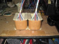
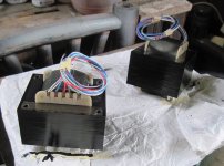
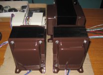
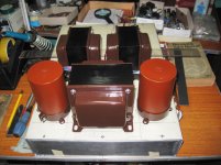
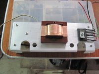
output transformer, made out of 0.35mm RM18 EI cores, 1 1/2 enter leg stacked 2 inches..
800 ohms plate to plate to 2, 4, and 8 ohm speakers, with tertiary winding for cathode feedback..
800 ohms plate to plate to 2, 4, and 8 ohm speakers, with tertiary winding for cathode feedback..
Attachments
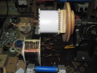
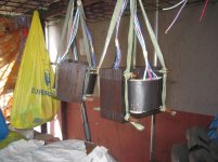
How convenient to be a winder. Lovely!
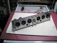
liker my other builds, this one is going to be from the ground up.....
liker my other builds, this one is going to be from the ground up.....
I find the tubes very hard to build
")
...with tertiary winding for cathode feedback..
How much is this ?
I would like to simulate a bit.
How much is this ?
I would like to simulate a bit.
same as the 8 ohm secondary winding...
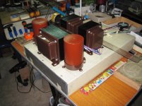
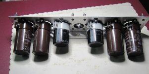
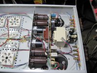
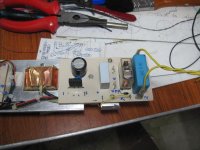
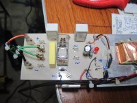
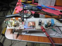
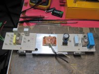
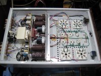
wiring up the power supply....
in this amp i am using a housekeeper transformer,
it functions to control two 12 volt relays,
one relay switches the main transformer to heat up the filaments,
and the other to short our the soft starting resistor supplying
the plate B+ for the 6C33 plates...
a three position switch at front panel is used to sequence these..
there is a dpdt paddle type main switch at the back to remove all ac going inside the box.
Attachments
-
 IMG_5087.JPG585.9 KB · Views: 157
 -
 IMG_5084_zpsdeea959d.jpg61.6 KB · Views: 125
 -
 IMG_5083_zps4686318f.jpg59.9 KB · Views: 126
 -
 IMG_5081.JPG575.1 KB · Views: 125
 -
 IMG_5082.JPG588.2 KB · Views: 119
 -
 IMG_5078.JPG544.7 KB · Views: 125
 -
 IMG_5071.JPG477.9 KB · Views: 149
 -
 IMG_2889.jpg440.6 KB · Views: 165
Hi Tony:
Seeing as the tertiary feedback winding is the same turns as the secondary, is this wound on as bifilar with the secondary?
I've been thinking of a setup where the CFB would be bifilar/matched to the secondary, and a set of taps would be put in the primary plate winding at the same number of turns from the B+ tap. Then a couple of big caps could be put between the CFB ends and the plate taps. That would effectively make twice as much primary winding bifilar coupled to the secondary. Sort of a mini Mac design or Crowhurst Twin Coupled. Since the % CFB would be low (maybe 10%), one might also consider a trifilar UL winding as well (for pentode types). The low %UL and %CFB would be compatible with the TV Sweep tubes, plus allow the typically lower screen Vdc.
Last edited:
- Status
- This old topic is closed. If you want to reopen this topic, contact a moderator using the "Report Post" button.
- Home
- Amplifiers
- Tubes / Valves
- Tony's 6C33 pp amp build progress....