I think the volume/balance arrangement needs looking at. As it stands you can short out either input at max volume.
Look at figs 7 and 9 here,
Potentiometers (Beginners' Guide to Pots)
Look at figs 7 and 9 here,
Potentiometers (Beginners' Guide to Pots)
I think the volume/balance arrangement needs looking at. As it stands you can short out either
input at max volume. Look at figs 7 and 9 here, Potentiometers (Beginners' Guide to Pots)
Yes, a resistor (1k-5k) on each input before the volume control should fix it.
There are no coupling capacitors at the outputs, so there could be loud noises (or worse)
when turning the power on/off, or when a supply fails. The amplifier could be damaged
from output DC if it has no input capacitor.
Last edited:
Yes, a resistor (1k-5k) on each input before the volume control should fix it.
There are no coupling capacitors at the outputs, so there could be loud noises (or worse)
when turning the power on/off, or when a supply fails. The amplifier could be damaged
from output DC if it has no input capacitor.
Hi all,
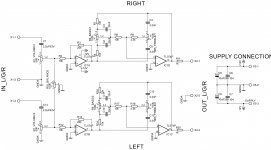
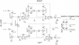
Here is the modified schematic as per your suggetions. Hope its all right this time. I have used a 1k resistor at input before vol control and 1uF coupling cap at output.
regards
prasi
Attachments

Hi all,
Here is the modified schematic as per your suggetions. Hope its all right this time. I have used a 1k resistor at input before vol control
and 1uF coupling cap at output.
Seems ok, but it depends. What are your source components and their impedances, and what is the output component and its input impedance?
Hi Rayma,
I am planning to use a general purpose DVD/Blueray player as the source. on the output side planning to use the DIYAUDIO
honey badger amp / APEX kelvin amp.reg
The source should be ok. The honey badger has around 25k input, so you'll want at least 1uF for the output cap.
If the other amp is also fed by the circuit, the cap would need to be larger, maybe twice as large.
I would increase the value of R10 to 100k or more, as it needlessly loads the output cap.
Remember to use small decoupling caps near each op amp's supply pin, around 0.1uF.
Last edited:
here are answers to the points that you mentioned.
1. by output cap do you mean C15/C16? They are already 1uF 63V. For the other amp ( APEX amp), I will try to use 2.2uF.
2. I will increase the R10 to 100k.
3. Decoupling caps are used (right of schematic -C6, C7: 104)
apart from the above any other construction/ layout tips.
I am trying to layout the PCB but its quite a job!.
reg
prasi
any other construction/ layout tips.
I am trying to layout the PCB but its quite a job!.i
You can post your layout here, I'm sure there will be a few suggestions.
You can post your layout here, I'm sure there will be a few suggestions.
Hi Rayma and others,
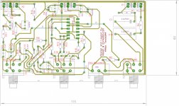
Finally I was able to layout the PCB. I am attaching the layout (and the final schematic for convenience).
Appreciate very much if you can suggest improvements/corrections.
some design values and considerations that went into the layout.
1. pots to be pcb mounted with adequate spaces between adjacent pots for operation of knobs(of reasonable sizes).
2. width of the traces is kept as 0.6096mm (24 mils). Hope this is sufficient for current levels.
regards
prasi
Attachments
Last edited:
1. pots to be pcb mounted with adequate spaces between adjacent pots for operation of knobs(of reasonable sizes).
2. width of the traces is kept as 0.6096mm (24 mils). Hope this is sufficient for current levels.
The trace widths should be ok. The two channels usually are kept more separated from one another. Is there a constraint on size or shape?
Also, when there is no ground plane, the ground routing is best kept as compact as possible for each channel to minimize parasitics,
and then the two channels' grounds can be connected at the main power capacitor or regulator.
Last edited:
"Is there a constraint on size or shape? "
no, there is no constraint on the size or shape of the PCB. I do not want to run separate wires from PCB to pots and so on. Hence wanted to have PCB mounted pots with min 18mm dia knobs on the chassis.
"Also, when there is no ground plane, the ground routing is best kept as compact as possible for each channel to minimize parasitics,
and then the two channels' grounds can be connected at the main power capacitor or regulator."
Wow, that's a whole different ball game altogether and it may well be beyond my abilities, unless someone pitches in and helps with the layout. One thing that I would like to know from you is, whether this PCB will work with reasonable amount of fidelity and intended purpose with most amps (chip/SS). or should I build and see whether it works?
another option that I would like to know is whether I should use to two TL072 op amps (one for each channel for bass and treble)
also instead of tl074, would i get better fidelity with OPA 4134?
thanks and regards
Prasi
whether this PCB will work with reasonable amount of fidelity and intended purpose with most amps (chip/SS).
or should I build and see whether it works?
If you have a source for inexpensive pcbs and just want something that works soon, I'd go ahead and get some experience along the way.
Layout of pcbs is an art in itself. Using a couple of dual op amps would have many advantages, and most types of op amps do come in duals.
On the other hand, if you want to do a lot of experimenting with different circuits and parts, you could use a solderless breadboard instead,
where everything can be easily reconfigured and reused. I've used them a lot and have had good results, like 10ns edges on drivers for
switching power supplies.
Last edited:
hi,
just need a little info. I came across rod elliots project 97. But I am little apprehensive about using it due to copy right clause mentioned at the bottom of page (Hi-Fi Preamplifier). so I wont be able to post the schematic and the pcb layout here if i understand the clauses correctly.
regards
prasi
I came across rod elliots project 97. But I am little apprehensive about using it
due to copy right clause mentioned at the bottom of page (Hi-Fi Preamplifier).
That should work well for you, and cheaper than having your own board made.
Posting the link here is good enough.
Hi,
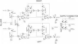
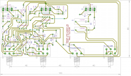
I have made a second layout using 2 OPA 2134 and tried to the star grounding scheme. Although I have not separated left and right channel grounds, I have tried separate power ground and joined all at the power entry point. The schematic and layout attached.
Any comments ?
regards
Prasi
I have made a second layout using 2 OPA 2134 and tried to the star grounding scheme. Although I have not separated left and right channel grounds, I have tried separate power ground and joined all at the power entry point. The schematic and layout attached.
Any comments ?
regards
Prasi
Attachments
I have made a second layout using 2 OPA 2134 and tried to the star grounding scheme.
Although I have not separated left and right channel grounds, I have tried separate power
ground and joined all at the power entry point.
There should be small decoupling caps right at the power supply pins of each op amp.
I'd try to shorten the balance and volume control grounds. You could run them to the
left of the input caps, and move the signal trace that goes between the balance and volume
controls lower to make way for them. Also I'd separate the volume control grounds,
with a trace for each going to the main ground. Is there a reason that the channels share a
ground, both at the inputs and outputs?
Last edited:
OK will do. can polyester 104 should be ok, right?There should be small decoupling caps right at the power supply pins of each op amp.
OK. will do. I think now I got the hang of it on exactly how to do it.I'd try to shorten the balance and volume control grounds. You could run them to the left of the input caps, and move the signal trace that goes between the balance and volume controls lower to make way for them.
there is no reason why they share a common ground. I had, in my earlier pre-amp twisted the left and right ground wires together and inserted them at ground i/p. there was no issue with any hum/noise. that's why i thought it might work here also. here is what I will do. I will use three separate grounds, One for left channel, one for right channel and one for power and then combine them all near power i/p at a convenient location.Also I'd separate the volume control grounds, with a trace for each going to the main ground. Is there a reason that the channels share a ground, both at the inputs and outputs?
regards
prasi
- Status
- This old topic is closed. If you want to reopen this topic, contact a moderator using the "Report Post" button.
- Home
- Source & Line
- Analog Line Level
- Tone control TL074