hailteflon said:As I recall, many of the viscous cueing devices are more of a paddle moving through a puddle of the viscous silicone. Mark
Or a cone dropping into a conical seat (drops quickly at first, then decelerates as the stylus touches the LP).
I hope to get a run at this tomorrow and will give bobkens idea a try out.
Will report and let you know. I have the curved bit, rising post and cylinder all to hand so the cam etc is what I would need to work out.
Having looked at a wide range of arms there seems to be just a few versions, made by just a few manufacturers, namely the rega one, the jelco and sme I think.
Fran
dnsey said:Have a look at some old cassette decks: the load/eject mechs are often damped using a dashpot which could easily be removed and reused.
There's a thread with a link to a free sample dashpot here.
Another option would be magnetic damping. If you drop a magnet through a copper, brass or aluminum tube it will fall slower than through free space. No messy fluids, just a hole in an aluminum block and a small neodymium cylinder magnet would do the job.
Fran,
I have made several of these devices and some other constructions which require a smooth but damped movement when actuated.
Having tried all kinds of 'conventional' lubricants for this purpose, nothing I ever found was entirely satisfactory, and the reason is that lubricants are designed to reduce friction between sliding surfaces, whereas what is required here is almost the converse of this. What is needed is something which actually increases the friction between the bare surfaces, but in a linear or constant manner, also giving a degree of resistance to movement due to accidental knocks/vibration etc.
Normal lubricants do not exibit these properties, and no matter how viscous they are, once the actuation or movement begins the resistance to further movement seems to reduce in all cases I have investigated. So, it requires more effort to start the movement, but instead of remaining consistent, once 'on the move' the required forces are reduced and/or the motion tends to speed up.
For many years I have used a product made in the UK by Rocol, called Kilopoise, and this is expressly made for just this purpose, including binocular fucussing adjustments etc. It is available in several different grades, and I have found that 2 of these have covered all of my requirements such as P-U lifts and rotary controls (pots and switches) when the cheapest scratchy jerky movement of these can be made to feel 'expensive' and very nicely damped for feel when in use. This was purchased from Farnell maybe 20+ yrs ago, but it seems that Farnell don't list this product now. However a quick Google search on Kilopoise indicates that it is still available, almost worldwide.
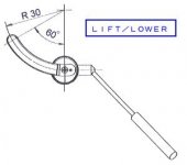
Incidentally, referring to my earlier sketch, if you attach the actuating lever to the cam so that it is horizontal and in line with the flat on the cam, rather than upright as I showed this, it might work out better for your purposes. Then, when the lever is down against the base board the lift is at its lowest position, and raising the lever will also raise the P-U arm. Also, when the TT is not in use, the lever will lie down on the base board and when records are playing there is no chance that due to vibration or whatever (most unlikely anyway) that the lever will rotate from vertical, and consequently lift the arm whilst the record is still playing.
Regards,
I have made several of these devices and some other constructions which require a smooth but damped movement when actuated.
Having tried all kinds of 'conventional' lubricants for this purpose, nothing I ever found was entirely satisfactory, and the reason is that lubricants are designed to reduce friction between sliding surfaces, whereas what is required here is almost the converse of this. What is needed is something which actually increases the friction between the bare surfaces, but in a linear or constant manner, also giving a degree of resistance to movement due to accidental knocks/vibration etc.
Normal lubricants do not exibit these properties, and no matter how viscous they are, once the actuation or movement begins the resistance to further movement seems to reduce in all cases I have investigated. So, it requires more effort to start the movement, but instead of remaining consistent, once 'on the move' the required forces are reduced and/or the motion tends to speed up.
For many years I have used a product made in the UK by Rocol, called Kilopoise, and this is expressly made for just this purpose, including binocular fucussing adjustments etc. It is available in several different grades, and I have found that 2 of these have covered all of my requirements such as P-U lifts and rotary controls (pots and switches) when the cheapest scratchy jerky movement of these can be made to feel 'expensive' and very nicely damped for feel when in use. This was purchased from Farnell maybe 20+ yrs ago, but it seems that Farnell don't list this product now. However a quick Google search on Kilopoise indicates that it is still available, almost worldwide.
Incidentally, referring to my earlier sketch, if you attach the actuating lever to the cam so that it is horizontal and in line with the flat on the cam, rather than upright as I showed this, it might work out better for your purposes. Then, when the lever is down against the base board the lift is at its lowest position, and raising the lever will also raise the P-U arm. Also, when the TT is not in use, the lever will lie down on the base board and when records are playing there is no chance that due to vibration or whatever (most unlikely anyway) that the lever will rotate from vertical, and consequently lift the arm whilst the record is still playing.
Regards,
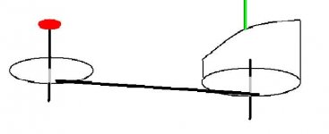
Here's an alternative idea (please excuse the crude 'Pant' rendering!)
The red control knob is coupled to disc on left, whose motion is transmitted to disc on right by coupling rod.
This disc carries a 'ramp' cam, which is followed by the green lift rod.
Any or all parts could be damped if required, but the rotary action allows smooth operation without damping.
BTW, Micro-Tools carry a reange of items (including damping greases) which are handy for this kind of project.
Attachments
OK, I have the cam made as per bobken's drawing (well kinda anyway)! The cam gives a movement of about 4.5mm at max. i measured teh movement on my RB300 and it has about 3mm or so. So I should get enough to rise it an appropriate amount.
So now I have a rise and fall mech, a piston and cylinder, a curved arm rest but just need to get it all together.... and thats the next job.
I am taking some photos and will put them up shortly...
Fran
Ps, the "coupled discs"/dnsey method would have worked too - in fact that would have been a good system because I could have hid nearly all of it under the armboard. Thats one for future reference. I would have probably gone for it if I hadn;t already had this one half made.
OK, so heres what I managed to do. The mechanism works OK although is a little sticky and is undamped. I started looking at it critically and there is just no way with my skills that I could do a damped pot and make it work out OK. So I got the minimum I wanted - a means to raise and lower the arm. Yes, it s abit sticky, but I'm hoping that that will settle down a bit.
Pic of the unassembled bits:
And then the device put together:
And then a blurry shot of it mounted in the mounting post clamp:
So it works. Bobkens idea of the angled block lit a light bulb for me and I used the SS tubing I had, cut it away and then bent it to 90deg. After that you can see for yourselves how it worked.
Thanks to all here - I literally couldn't have done it without the help and ideas here!
Fran
Pic of the unassembled bits:
An externally hosted image should be here but it was not working when we last tested it.
And then the device put together:
An externally hosted image should be here but it was not working when we last tested it.
And then a blurry shot of it mounted in the mounting post clamp:
An externally hosted image should be here but it was not working when we last tested it.
So it works. Bobkens idea of the angled block lit a light bulb for me and I used the SS tubing I had, cut it away and then bent it to 90deg. After that you can see for yourselves how it worked.
Thanks to all here - I literally couldn't have done it without the help and ideas here!
Fran
Hi Fran,
Well done, and its amazing just what can be achieved with a bit of thought, effort and ingenuity.
What will possibly be better here is to only damp the rotary movement of the cam in the sleeve it revolves in. Try some really thick grease to see what happens, but getting some Kilopoise will certainly do exactly what you need for this. It is (or certainly was)available in quite small quantity like toothpaste-tube size.
Assuming that the piston which moves up and down is a reasonably good fit in the tube it slides within, you would do better to use some thinner oil for this as there is a large sliding area of contact and anything too 'heavy' in consistency will not allow the arm to drop so readily. All you need for the vertical piston is a smooth but 'easy' lubricated sliding action, and all of the damping can then be done on the shaft of the cam. Certainly using Kilopoise only on the rotating cam gives me a very precise and suitably slow change from 'up' to fully 'down', and because of the 'drag' created by this product it is impossible to lower the arm quickly even if attempts are made to do this. The effect is like when focussing HQ binoculars or cameras, with a smooth but steady movement, which cannot be jarred/jerked or operated at any higher speed.
With my set-up I can just start to lower the actuating arm from vertical with a slight initial touch, and it then lowers gracefully and unaided at a constant rate, mainly due to the weight of the knob at the end of this rotating lever, and partly due to the pick-up arm's weight.
A bit of experimenting was needed to get the right damping compared with the weight (and length, as this affects the rotational 'moment') of the arm, but the result is far steadier and more predictable than if I lower the arm manually.
To get this balance just right, you have several 'variables' to play with including the drag due to the (damped) surface area of the cam which is in contact with the sleeve it rotates within, the weight of the knob on the arm, and its position relative to the centre-line of the rotating cam.
This can be done quite quickly and experimentally, by final adjustments to the mass of the knob, and/or its position along the shaft when, of course, if the mass is moved further from the cam, it will have a greater effect (like increasing the mass of the knob). I usually finalise this with blobs of modelling clay in place of the knob initially, until I am happy with the 'unaided' rate of descent, and then make a knob of approximately the same mass.
You don't even need a sensitive pair of scales for this, as a 12" ruler placed at right-angles across a round pencil (like a see-saw) for a fulcrum will be fine for this purpose. Balance it approximately without anything else, and then place the chosen blob of whatever at one end, and 'adjust' the weight of the proposed knob until the whole thing balances with this knob on the opposite end of the ruler.
Finally, if you do as I do, which is to drill a longish hole in the centre of the knob, final adjustments for perfection can be achieved by sliding the knob down the lever until satisfied, and then fixing it to the shaft in this position.
I have 2 of these home-made P-U lifts presently, and both are as satisfying to use as my SME 'V' arm lift and a Fidelity Research arm lift (2 very high-quality and well-engineered pickup arms), which also work on this same cam principle, actually.
Regards,
I made my lift using parts from an old Toshiba TT and modified to fit my DIY arm,. For damping I used was a smear of resin from epoxy glue, not the hardener nor combining both or you will glue your parts together. The stiction of the resin felt to my fingers almost as stiff as the lubricant Toshiba used on their TT when I disassembled their lift from it. So I tried it and it works well enough, not as damped and the stuff used in the Toshiba but felt similar and to my liking. But you can buy damping silicone out there if you like. Other threads here have noted these .
BTW I like some of the other lift ideas here and that makes DIYing great!
BTW I like some of the other lift ideas here and that makes DIYing great!
Just got an email back from jelco. The arm lift is listed as 3500 yen ea plus 1500 for post (EMS) giving a total of 5000yen. XE gives that as about €30. Not bad really - If I hadn't been successful I would have bought one.
I'm not in a position ot do a group buy but if someone goes for it, I will join in.
I'm not in a position ot do a group buy but if someone goes for it, I will join in.
Hi,
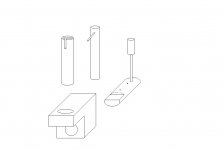
A simple but effective pickup lift can be made out of readily available materials, for not much cost, and with minimal tools like a miniature hacksaw, file, drill etc.
If I can show an attachment (it didn't when I checked "Preview Reply"!), this should become clear, and the hardest part for anyone without a good workshop will probably be drilling the base where 2 holes are needed at right angles to each other. The materials can be softer metals like aluminium or even acrylic etc., which will make any drilling sawing and filing less onerous, and will be quite adequate for this purpose. Incidentally, knitting-needles, which are available in plastic and highly-polished alloy in all different diameters, are very useful for making thinner rods or bars, and are also easy to obtain and inexpensive.
The main parts are the slotted tube which needs to be chosen to suit a piece of round bar as a close 'slip fit', and the inner bar which has the rod inserted at right angles to form the pick-up arm support. The cam is made also from (the same?) round bar, with a part of it removed by filing, and this is inserted from the back of the base-block, with a couple of small pins at each side of the base being fitted in the round bar to locate this cam, to prevent lateral movement. The second pin is inserted after the cam is located in the base, and if provision is made for a washer at both faces of the base, this will prevent any sticking or scraping when the lift is in use.
Then the tube is glued (if the fit is not tight enough without) into the vertical hole in the base, with the slot aligned suitably for the arm position, and the inner rod is slid down so that the arm-lifting peg is within the slot. When rotating the cam via the handle, the inner rod and arm-lifting peg will then move up and down, as will the arm if this is positioned appropriately.
No dimensions are critical, and it is best to draw the various parts out to scale first to establish the required lifting-action of the cam, and the positioning of the entire lift compared with the arm and the base-board of the turntable, to ensure that it all works as intended.
I hope this may help, and can anyone who might be interested tell me how to convert a bitmap (bmp) image into something suitable to attach here. This appears to be the problem with my attachment which I drew in Paint and cannot be shown in this format according to the Forum messages.
Hi,
What will be the best suitable shape of the rotating cam ? Will it perform better if there is a slanting towards a side so that the arm lifting peg can easily slide down ? Please suggest...
Best regards,
Bins.
Attachments
- Status
- This old topic is closed. If you want to reopen this topic, contact a moderator using the "Report Post" button.
- Home
- Source & Line
- Analogue Source
- tone arm lift