I'd be surprised if you needed more than 100 pF. It's actually with slower, high capacitance transistors where you need these caps, and the "slower" the more you need. The C-B cap changes radically with voltage, and it's the CHANGE in the cap value you need to swamp out. A changing capacitance causes a negative resistance to appear (math is complicated, but thet's the gist of it).
This is why you look for low Cob drivers.
2sc1384 had a decent 200MHz with 11pF typical cob, and a max of 20pF.
The replacement has 140MHz with 14pF typical cob.
I made some frequency tests this night.
I don't see any kind of oscillation. I do see some movement on the top part of the sine wave when it clips. There's a little wiggle on the clipped top side. but before clipping the sine is clean 20Hz-20kHz.
The output is fairly linear. I loose about 5-10% amplitude on the high end.
Also there's something strange happening past 22kHz. the sine becomes fuzzy from the top down, and as I sweep slowly the amplitude decreases until flat line, then goes up again and reaches full peak again at 23-24kHz and looks very good at 25kHz (as much as I could test for). Probably can do a bit more to 30kHz.
I don't know what is happening, seems like the signal is inverting when rising again past 22.5kHz.
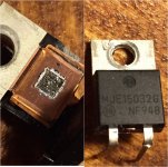
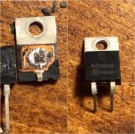
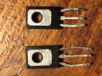
I decided to crack open two burnt output MJE15032 transistors. I found two types at the store, both in the same box.
Is any of the two a fake? Or at least a decent copy/implementation? I could replace them all for one kind if there's one legit.
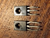
I will have to take both boards out again. The right channel to replace the 0.5ohm resistors that I burnt (and used the old ones from the amp), and the left channel I want to replace the driver transistors with 2sd669ac (which I don't think are legit as well)
2sd669 has a gain of 245 and 2sb649 has a gain of 270 (made with cheap dmm function). As I read the original had a lower 170ish or so. They do look nice as a product, not a cheap clone.
I don't see any kind of oscillation. I do see some movement on the top part of the sine wave when it clips. There's a little wiggle on the clipped top side. but before clipping the sine is clean 20Hz-20kHz.
The output is fairly linear. I loose about 5-10% amplitude on the high end.
Also there's something strange happening past 22kHz. the sine becomes fuzzy from the top down, and as I sweep slowly the amplitude decreases until flat line, then goes up again and reaches full peak again at 23-24kHz and looks very good at 25kHz (as much as I could test for). Probably can do a bit more to 30kHz.
I don't know what is happening, seems like the signal is inverting when rising again past 22.5kHz.
I decided to crack open two burnt output MJE15032 transistors. I found two types at the store, both in the same box.
Is any of the two a fake? Or at least a decent copy/implementation? I could replace them all for one kind if there's one legit.
I will have to take both boards out again. The right channel to replace the 0.5ohm resistors that I burnt (and used the old ones from the amp), and the left channel I want to replace the driver transistors with 2sd669ac (which I don't think are legit as well)
2sd669 has a gain of 245 and 2sb649 has a gain of 270 (made with cheap dmm function). As I read the original had a lower 170ish or so. They do look nice as a product, not a cheap clone.
Attachments
Becoming 'fuzzy' is a classic sign of high frequency oscillation.
That's after clipping so it doesn't bither me.
@Welcome
Yes, originally there were 2sd315 in to-66 case. And they would have been toast now if I wouldn't have replaced them.
Becoming 'fuzzy' is a classic sign of high frequency oscillation.
Ah sorry, you were refering to the fuzziness past 22khz. I hope I can capture what is happening and show a video
starting to oscillate during a clipping incident could burn out the amplifier and lead to speaker damage.
I thought that if only the small clipped part "wiggled" a bit there's not enough energy there to cause damage.
I will compare with the peft channel and see how that looks. Also I want to compare the weird oscillation past 22khz. There seems to be something that goes out of phase and cancels out the sinewave becoming flat line at 22.5khz or so. Then goes up again. While going down/up there's fuzziness inside the sine.
The wiggles on the top is probabaly power supply ripple being conducted through saturated output transistors. Boot strap drive will attempt to get very cose to the + rail, and if that is changing, the clip point does too. With a single supply amp, the negative going half clips at ground, which won't change.
Concerning the strange frequency response, it sounds like there is a notch filter somewhere in the signal path. Why it would be oscillating when driven hard up there is anybody's guess - if in fact that is what is happening.
Concerning the strange frequency response, it sounds like there is a notch filter somewhere in the signal path. Why it would be oscillating when driven hard up there is anybody's guess - if in fact that is what is happening.
starting to oscillate means that the stability margins are eroded to the point that the amp has become unstable.I thought that if only the small clipped part "wiggled" a bit there's not enough energy there to cause damage.
I will compare with the peft channel and see how that looks. Also I want to compare the weird oscillation past 22khz. There seems to be something that goes out of phase and cancels out the sinewave becoming flat line at 22.5khz or so. Then goes up again. While going down/up there's fuzziness inside the sine.
You should be trying to get the stability margins back to a level such that for various temperatures and loads and operations there is not a tendency to become unstable.
Any word on the output transistors (mje15032)? Do they seem like fakes? It's strange as there are two types with different markings but inside I see copper in both and the dies have similar (if not identical) dimensions.
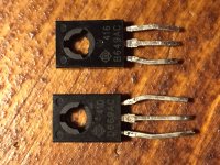
Still need to crack one 2sd669 and see if the die is minuscule or something normal for that size.
Still need to crack one 2sd669 and see if the die is minuscule or something normal for that size.
The 649/669 are some kind of clone of the obsolete Hitachi.
But the originals are one of the highest SOA To126 ever available and outperform most T0220 for both power and speed.
That leads me to expect a "big" semi on the copper slug.
It would be interesting to see if what is actually used meets with my expectation?
But the originals are one of the highest SOA To126 ever available and outperform most T0220 for both power and speed.
That leads me to expect a "big" semi on the copper slug.
It would be interesting to see if what is actually used meets with my expectation?

I decided to crack open two burnt output MJE15032 transistors. I found two types at the store, both in the same box.
Is any of the two a fake? Or at least a decent copy/implementation? I could replace them all for one kind if there's one legit.
ON has a couple of different pacakging facilities. Both look legit, but the 2nd one looks like a major QC problem. They used WAY too much silver epoxy to attach the die. That will increase the thermal resistance and make it run too hot (internally - the case temp will not go up).
ON has a couple of different pacakging facilities. Both look legit, but the 2nd one looks like a major QC problem. They used WAY too much silver epoxy to attach the die. That will increase the thermal resistance and make it run too hot (internally - the case temp will not go up).
Ah, ok. Then I will get the first type and have them all the same.
They are obsolete.Any leads to sourcing legit d669/b649?
Only clones and fakes are now available, unless some honest and benevolent Members have a stash of old stock that they are prepared to share.
The 649/669 are some kind of clone of the obsolete Hitachi.
But the originals are one of the highest SOA To126 ever available and outperform most T0220 for both power and speed.
That leads me to expect a "big" semi on the copper slug.
It would be interesting to see if what is actually used meets with my expectation?
These are not "clones". They are either NOS originals or outright fakes. "Clones" would not be marked with Hitachi's logo. The dies will in fact be small (under 2mm) even in originals. fT is high and capacitance is low, which requires a small die. And mm^2 per mm^2, small dies hold up better for SOA than large ones. You would need proper test equipment and methods to determine if they are real or fake unless it's extremely obvious from cracking one open. If they put in "cheap" BD139/140 dies in them, they would probably work fine in the application. The high fT, low Cob, and high SOA for this device type are highly desirable, but not essential in an amplifier with relatively low open loop gain and a single +48V rail. If you had a low enough fT (under 10 MHz) it may give you grief, but if it's even close to being in familiy it would work.
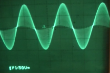
By pure chance I stumbled upon a screenshot of a waveform that looks exactly like my amp's at about 22-22.5khz.
It starts looking like this, then when I increase the frequency it goes down in amplitude (still looking like this) until it flatlines (even if the volume is way up). Then as I increase the frequency even more it starts to rise again (with maybe a phase shift) looking like this picture and it clears at about 23khz or so and looks great again.
It starts looking like this, then when I increase the frequency it goes down in amplitude (still looking like this) until it flatlines (even if the volume is way up). Then as I increase the frequency even more it starts to rise again (with maybe a phase shift) looking like this picture and it clears at about 23khz or so and looks great again.
Attachments
- Status
- This old topic is closed. If you want to reopen this topic, contact a moderator using the "Report Post" button.
- Home
- Amplifiers
- Solid State
- to92 transistor replacement