I need to mount about 20 TO-3P devices on a couple of heatsinks as part of a project I am working on. I have lots of lattitude about how I can do this - the heatsinks will be internal to a box with some forced air cooling. Looks are not important.
Checking the part datasheet I see that the thru hole is only 3.2mm diameter. My heatsinks are heavy-duty cast aluminum and I will have to drill and tap blind holes in them if I want to mount the transistors the conventional way. 3.2mm is too small for a #6-32 machine screw. I could go for a 3mm but in the USA this is not easy to find. Any of these sizes are pretty tiny and I am concerned that sooner or later I will snap off my drill or tap and that can be a real bummer (I know this from experience).
One option I am eyeing is a "clamp" to hold down the devices and insulators. I have seen created from a section of aluminum u-channel that is placed across the plastic part of the package and then tightened down. This would need to span several devices and I am concerned about uneven pressure. I've never attempted anything like that myself, so if anyone has tips on that please post them.
If I should go ahead with the conventional tapped hole I will need to use 3mm or #4-40 size. These seem rather small, however, I could drill a hole and then use a thread-cutting screw, which would at least save me the risk of snapping a tiny tap.
If anyone has some advice on how I should tackle this, please let me know before I make a series of blunders.
I usually get on with 3mm screws OK.
I use a drill bench press to hold the drill steady. You can pick one up on ebay cheap enough.
So long as you don't push too hard the drill wont snap.
I always use some cutting oil with the 3mm tap and mine has lasted for years.
The oil takes some of the stress off the tap.
I use a drill bench press to hold the drill steady. You can pick one up on ebay cheap enough.
So long as you don't push too hard the drill wont snap.
I always use some cutting oil with the 3mm tap and mine has lasted for years.
The oil takes some of the stress off the tap.
If anyone has some advice on how I should tackle this, please let me know
before I make a series of blunders.
Take a look at these. Tapping smaller than #6 can be problematic, but at least it's not a TO-220.
If you use a multi-device clamp, clamping more than two devices requires special measures.
Electronic Components and Parts Search | DigiKey Electronics
https://www.aavid-kunze.com/en/prod...e-transistor-clips,36/serie-ku-4-to247-264,80
Last edited:
Hi Charlie,
Have you thought about enlarging the hole on the TO-3P part? I once did that
when I wanted to mount some Fairchild mosfets on a heatsink with existing
6-32 holes. Pretty quick job with a drill press and the mosfets did not appear
to have suffered any damage.
Cheers,
Dennis
Have you thought about enlarging the hole on the TO-3P part? I once did that
when I wanted to mount some Fairchild mosfets on a heatsink with existing
6-32 holes. Pretty quick job with a drill press and the mosfets did not appear
to have suffered any damage.
Cheers,
Dennis
Have you thought about enlarging the hole on the TO-3P part?
This can work if the hole is carefully deburred.
Hi Charlie,
Have you thought about enlarging the hole on the TO-3P part? I once did that
when I wanted to mount some Fairchild mosfets on a heatsink with existing
6-32 holes. Pretty quick job with a drill press and the mosfets did not appear
to have suffered any damage.
Cheers,
Dennis
Hmmm, had not thought about that but now that you mention it... not a bad idea at all. The hole is lined with an insulator (plastic) material. The OD of the threads on a #6 screw is very close to the hole ID, maybe 3.5mm versus 3.2mm. So I could probably open it up so that it would clear the #6 screw without too much worry. But that would not leave much error for drilling the mounting holes. The devices are already soldered to the amp PCB so side-to-side movement is slim to none. Marking and then drilling would probably lead to small location errors (am I AR or what?).
I might be able to temporarily clamp down the amp module onto the heat sink and drill with the bit that will "open up" the mounting hole, plunging the bit though the device hole and then into the heat sink a couple of mm. The head of the bit would establish the hole center. I could then remove the amp module and continue drilling with the correct bit size for the hole, which would then be tapped to #6. Might not be too bad this way.
...
The devices are already soldered to the amp PCB so side-to-side movement is slim to none.
...
Should have been mounted first, then soldered unless you had them clamped in place for alignment.
Should have been mounted first, then soldered unless you had them clamped in place for alignment.
Bought them assembled.
...I am concerned that sooner or later I will snap off my drill or tap and that can be a real bummer...
If you tap then use one that flow forms the threads rather than cuts them.
Less likely to break.
Maybe need to buy this from a proper industrial supplier rather than a hardware store.
Best wishes
David
DUG is right about the solder sequence.Bought them assembled.
After you get done mounting the things, its best to relieve any mechanical stress by re-heating all the solder joints that are mounting larger devices or esp any parts going off the PCB. including transistors w /HS, connectors, pots with shafts, etc,. Any stresses combined with heat cycling leads to solder connection failures.
I have successfully re-drilled the hole to ~3.5mm to take an M3.5 screw.Hi Charlie,
Have you thought about enlarging the hole on the TO-3P part? I once did that
when I wanted to mount some Fairchild mosfets on a heatsink with existing
6-32 holes. Pretty quick job with a drill press and the mosfets did not appear
to have suffered any damage.
Cheers,
Dennis
The plastic land around the hole is pretty big and leaves plenty of room for the bigger bolt hole.
But I prefer the clamping method.
I use M4 placed on each side of EVERY device.
The cheapest clamp bar is strip mild steel. I use 4mm by 15mm. 3mm by 12mm would do but is a bit flimsy and may bend as you tighten down.
One advantage of the clamp bar is that as you tighten down the device does not rotate straining the soldered lead outs.
This becomes a big advantage after you have taken apart the amplifier for yet another check-over.
Attachments

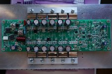
My go-to heatsink mounting for over a dozen amps now has been #4 screw (4-40) drill and tap into aluminum and use hex socket cap screw and Bondhus allen driver. Works for TO-3P, TO-247, TO-220, TO-126. The tap is small enough to easily work without requiring too much force that can break a larger tap. Blind drill and tap is no problem, has enough threads with only 0.3in deep hole. Oh, and the 6-32 can take the M3 nylon insulator bushing needed on TO-220 metal tabs.
Latest example with TO-220 and TO-247 blind tapped in aluminum:
Latest example with TO-220 and TO-247 blind tapped in aluminum:
Last edited by a moderator:
Thanks for the thoughts on drill and tap for a #4 screw. I will pick up the necessary tools to do that. I am sure that there will be a need for them in my future...
I think I will try my u-channel idea. The L12-2 amp boards that I will be using have two devices next to each other, but far enough apart that I could get a #6 or #8 screw in there (the sides of the devices are insulated). I can buy 3mm thick 25mm base x 25mm side u-channel that is pretty flat. I would cut a section that would cover the package, drill a thru-hole, then use a screw and washer to clamp the u-channel on top of the devices. This also would prevent the boards from moving around. Being 3mm thick, I don't expect any flex from the channel under the mounting torque used.
The advantage would be that I can drill fewer holes, and drill thru holes. These would come out in between the fins of the heatsink on the opposite side, and there is plenty of room for the screw head. This should make it very easy to assemble.
I have yet another set of amp boards (different type) that I need to build from parts + bare board. I will drill and tap these for the #4 screw thread and use the socket cap screw (great suggestion! had not thought of those) to secure each device to its heat sink. Also, will plan to solder devices only after mounting.
One other question, about fasteners.
Zinc coated steel would be OK, or not because it might become magnetized?
Stainless steel fasteners?
Other?
What is the preferred material for fasteners that will go thru the output devices?
Also, I have seen some people using Belleville washers instead of split lock washers. Anyone do that? The BW would deliver more even hold down force around the screw.
Last edited:
- Status
- This old topic is closed. If you want to reopen this topic, contact a moderator using the "Report Post" button.
- Home
- Amplifiers
- Solid State
- TO-3P mounting options