It is probably an overall grounding issue more than anything else. If you could post an overall system diagram of your audio setup this could help troubleshoot the issue
I have built a 3rd order crossover using TL084's and it is completely silent (and sounds great)
Once again I have the complete schematic and PCB diagram however it was a new prototype Mr. Erath made for me off of his commercial circuit and even though he has passed I am hesitant to post it on the web.
I have used the Marchand XM1 for decades and it is fantastic. I have always assumed the issue with this project was the layout but the easiest change was swapping opamps so I was going to try that first. However most think that would be a waste of time.
Last edited:
Ok, so changing the opamp to a "newer flavor" will most likely NOT fix the issue. The alternative is redo the PCB and possible modify the circuit. Being a circuit consisting of just 2 quad opamps you would think this was an easy project.
Unfortunately some time ago I had to disassemble my lab / bench and I have not had the opportunity to to rebuild one so I will have to hire out for this project.
Any starving EE's out there looking for work?
Unfortunately some time ago I had to disassemble my lab / bench and I have not had the opportunity to to rebuild one so I will have to hire out for this project.
Any starving EE's out there looking for work?
I had a Eureka moment over the weekend...
Since I have used the Marchand XM1's for years is systems and they were dead quiet why not bypass the whole XO section of the feedback unit and just use the FBN section as a stand alone. That way if the noise issue is with the XO section it will be alleviated and the feedback section can work UN-impeditedly.
If that works then a new FBN only pcb can be made and I can piggyback the Marchand XM1 on top.
UN-impeditedly ! Well it might doIt sounds like you are having fun though.
But yes looks like I will refrain from trying to reinvent the wheel.
"Ain't" got no time for that!
So with the help of a friend I ended up just redoing the circuit on a new pcb. However I have a couple of questions..
What does circle 3 and 4 actually do? I "think" they are shelf filters that do similar to a Linkwitz transform but I figured I'd ask people who know more than me.
Thank you in advance,
Troy
What does circle 3 and 4 actually do? I "think" they are shelf filters that do similar to a Linkwitz transform but I figured I'd ask people who know more than me.
Thank you in advance,
Troy

'4' is simply a unity gain buffer. The cap and resistor don't really serve any useful purpose as drawn and could usefully be linked out.
'3' is some kind of filter and would have a response like a shelf filter with the gain falling past a certain frequency point set by the pot.
'3' is some kind of filter and would have a response like a shelf filter with the gain falling past a certain frequency point set by the pot.
What does circle 3 and 4 actually do? I "think" they are shelf filters that do similar to a Linkwitz transform but I figured I'd ask people who know more than me.
Yes, they can have a purpose similar to an LT, but why do you ask? I think you should already know what you are trying to do. For example you talked about HF section but I don't know its relationship with posted image.
I don't think there is 'magic' or 'rocket science' with such circuit (except the fancy box). And to utilize it is not simple as to work properly it must work with other elements of the system. See the pots? How will you adjust the pot if not using proper tool?
I say, build something new. Define your objectives and you can always get free circuits from the net.
The circuit is already designed, built and working.
1. I am trying to decentralize it to make active speakers.
2. I am trying to make a more transparent high pass that has less effect on the top end.
As you can see in the picture, circuit boards have come a long way since that was produced.
And like computers the technology has gone full circle. I want to push the electronics back into the speaker like the originals.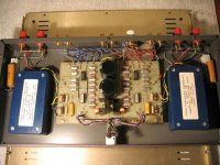

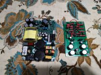
This is a new prototype pcb I had made off the original schematic. I plan to start stuffing them today and testing them this week. However I am trying to understand the circuit better. It is not my design and the audio genius who designed it has since passed so I can't ask him. Therefore I go to the next smartest people I know. The group collective here on DIYaudio.
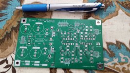

And these are prototype pcb's based off the original. Once I know it works I would like to see if I can improve certain aspects.
Layout, noise levels, component organization...
The actual negative feedback circuit for the woofer works like a charm and sounds fantastic.
It's the high pass that is the issue(noisey) and the desire to make active speakers that drive this project.
Layout, noise levels, component organization...
The actual negative feedback circuit for the woofer works like a charm and sounds fantastic.
It's the high pass that is the issue(noisey) and the desire to make active speakers that drive this project.
I'm confused as what exactly the device do. I guess the black box provides LF enhancement at the output of an LPF. And you have noise issue with the HPF. For your new build, make sure to use metal film resistors (carbon is noisy).
I see 2 quads per channel. One is the white op-amp. It seems that LPF and HPF use different op-amp?? Unfortunately you have designed the new PCB. Because it is better to have single or dual op-amps instead of quad because you have more op-amp options and you can choose suitable op-amp for suitable position.
Also, PSRR is problematic with most op-amp so you may want high-end power supply than the bad sounding 78xx/79xx.
Active op-amp-based crossovers are problematic for top quality audio so I think it makes sense to go over the top with the implementation (otherwise, DSP or passive could have been better).
I think I will start a new thread with the history, current state and destination. It is a fascinating tale of murder, mystery, tragedy and sorrow... JOKING!! It is a tale of an idiot (me) trying to bring a fantastic older technology up to modern standards.
Once I get all the pictures and documents together I will post a link to the new thread here.
Once I get all the pictures and documents together I will post a link to the new thread here.
And we have liftoff..
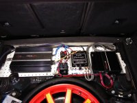
The new circuit does work and I am in the process of integrating it with the amplifier modules.
But a quick question on the "shelf filter" circuit.
Attached is what I think is the shelf filter to give the circuit it's 12db/oct boost below XO frequency.
If I open/remove the capacitor will it be just a gain stage? I need to defeat the boost/shelf function for a test but want to be sure first.
Thank you in advance.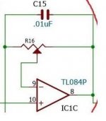
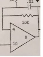


Thank you!Yes, just a variable gain stage.
I lifted the capacitor in the circuit and it worked as hoped. Sort of. I think in the car the full shelf filter is TOO much (too much infra sonics no midbass) but a little is needed.
I will put it back in the circuit and put another resistor in parallel to the first to keep the shelf filter but reduce the level of the circuit.
Another question, the potentiometers are VERY scratchy (30+ yrs old) but instead of changing them out I would like to use fixed resistors and set the gain at about 1/2 - 3/4.
Should I put a 10k from IN to GRD and a 3-5k from IN to WIPER(out)?
Thanks again!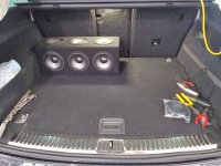


- Status
- This old topic is closed. If you want to reopen this topic, contact a moderator using the "Report Post" button.
- Home
- Amplifiers
- Solid State
- TL084 to???