We are using them in Brazil...hundreds of kits spread in my country
The big trouble is the derated power at 70 degrées celsius...... this is the power you should understand as safe.... the problem, the weak point of this device, is the power dissipation.
Watch graphics and calculate your stuff considering derated maximum safe operational conditions.
We are using them in our Brazilian kits because they are cheap, easy to find and not so bad...... problem is power dissipation...you should manage to reduce supply voltage and adjust you power amplifier parameters to use them inside the S.O.A. ..... and as i have said..... dissipation derated to 70 degrées is the power you may use as reference.
regards,
Carlos
Attachments
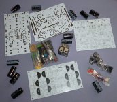
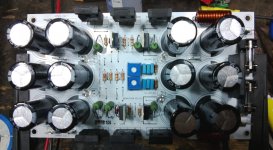
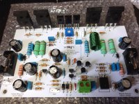
Here you see them in use
We are not accepting orders from foreign countries due we do not trust in our postal system now a days....in the future this may change, as in the past we had a very good service from them.
Joseph Siejack, from Canadá may order a hundred units..... Duda will come to Brasil and will get the package and after return to U.S. he will send pcboards to Joseph Siejack (Evette in this forum).
We do not think it is a very good transistor...we are using them because available in Brasil, easy to find and cheap...but we think there are much better choices.... MJL23194 and MJL21194 are a hell unstable devices (tested!) ... i have asked my people not to use them to avoid loose the guarantee.
regards,
Carlos
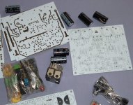
Attachments
Last edited:
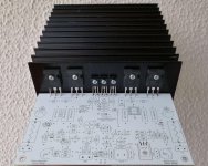
We have even reduced the supply voltage to 40 volts because of TIP35/36
To keep these transistors safe..also it is not suggested to use 2 ohms loads..when the original design was powered with 42 volts and able to face 2 ohms loads..... it could reach 350 watts RMS
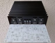
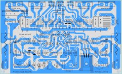
You see the new pcboard layout.... to Brazil only (sorry)
regards,
Carlos
To keep these transistors safe..also it is not suggested to use 2 ohms loads..when the original design was powered with 42 volts and able to face 2 ohms loads..... it could reach 350 watts RMS
You see the new pcboard layout.... to Brazil only (sorry)
regards,
Carlos
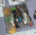
Attachments
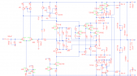
I have studied the stuff... reason why i am posting here my results
No intention to make advertisement of my stuff, as i do not sell the stuff, is DIY for free and also i cannot ship outside Brazil due to postal problems.
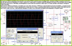
Here is the limit image about the TIP35, i have studied the limit of several transistors to apply into my power amplifier.....or, to apply to a 42 volts supply power amplifier.
regards,
Carlos
No intention to make advertisement of my stuff, as i do not sell the stuff, is DIY for free and also i cannot ship outside Brazil due to postal problems.
Here is the limit image about the TIP35, i have studied the limit of several transistors to apply into my power amplifier.....or, to apply to a 42 volts supply power amplifier.
regards,
Carlos
Attachments
I guess because he's using them in his latest kits. C5200's getting too expensive, DX?
Actually, I'm working on a little project - how to build a Real Amplifier using TIP35/36. Over 100W/8R without breaking the bank on semi's, transformer, heat sink, or caps. More to come when it's more than vapor.
The point of the exercise is all about the power stage (where the money is). I'm still deciding on the front end - whether to go op-amp, dual differential, blameless, or current feedback. Of course the choice needs to be made with the cheapskate in mind.... any votes?
Might do a variant with TIP142/147 darlingtons - just to say it can be done. I think discretes will offer better performance and won't cost a cent more if you use cheap (TIP31) drivers.
Brazllians loves to buy electronic parts in their neighboorhood
They do not like to buy from the internet...because of time of delivery and costs of delivery...also our postal system is not working fine these last 7 months.
They like the direct contact with humans...of course they have cell phones connected into the internet..high speed lines we have, and very cheap and more than 200 millions cell phones and twice of that of computers and notebooks...it is a cultural stuff.
Shops are selling fake units of 2SC5200..... and also not very easy to find them here...but the TIP line is something so easy as to buy a Coca Cola....also reasonable ones and very cheap ones...this is the reason, in Brazil, we are going to TIP35 to our Dx amplifiers.
Better than 2SC5200?.... no way!... just cheaper, easier to find.
I apologize for showing my amps, which are nowhere to be distributed to the international community ... the reason to show them and to demonstrate that I am experienced in contact with this component, which was heavily tested and I know what I'm saying worry .. ie .. with the power dissipation that is the Achilles heel of this component.
Last post in this thread...just answering you dear wg_ski.. someone that deserves my respect.
regards,
Carlos
Last edited:
I think it is good to make DIY amps from common parts. Sure you will have to de-rate the output stage a bit when compared to the top transistors, but cheap and available is a big plus to DIY especially for folks in countries where the semi market is less robust. I am currently making an amp using TIP102/107 Darlingtons. Why? Because I have some old junk containing these parts and others that is taking space in my closet and need to be used somehow. The output stage is a HEC circuit and uses small signal mosfets as the driver stage. I expect 20 to 25Wrms from one pair @ 8R. Also I can use some of the 25-0-25 @ 2A transformers from RS I have. 
Now, on to that Real Amplifier (t.m.) using TIP35's. It does take 2 pair, but will give 100W/8R even with crappy transformers and without bridging. Power will be 56/28/0/28/56, from two 20-0-20 200VA toroids. These are the same type normally used for gainclones and seem to be all over the surpuls market for next to nothing, unlike a typical 40-0-40 500VA unit that you have to pay full price for. I have about a dozen of them laying around, it's time to put some to use. And 35V caps are sufficient for the application.
The proto PCB will probably be just magic marker on bare copper board, and get real ones made when I'm done tweaking. I decided to go with the simple front end - and the exact same one has been used before. I've built power stages like this on MUCH bigger amplifiers. It is a class H and won't need anywhwere near as big a heatsink as is normally used on say, a Leach. I MIGHT be able to get a 2 channel in 1U with no fan. The only specialized components are the commutation doides, but just about any 8A ultrafast or schottky will work, and they run about $1.20 for the duals new. You can probably raid computer power supplies or burnt up car amps as a free source. Does anyone even bother to make fake SMPS rectifiers? Never heard of it (yet).....
Want to make it drive 2 ohms (or less)? Just parallel two everywhere where is one output.
Attachments
Is this rule of thumb for a 4 ohm reactive load or 8 ohm reactive load?use one of the SOAR spreadsheet calculators to model the output stage.
Bensen did one for Mosfets, Jan Didden has one.
I modified Bensen's for both FETs and BJTs.
Or use the simple formula
Maximum output power equals the total output device dissipation capability divided by Factor.
For FETs the Factor ~4
For BJTs the Factor is ~5 to ~6
2 125W devices = 250W of device dissipation.
Maximum output power ~ 250/5 to 250/6 = ~50W to 40W
2Pr gets to 100W to 80W
3pr gets to 150W to 120W. This last requires too high a supply voltage for 8ohms, so only possible into 4ohms speaker.
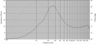
Current is highest at Zmin. Phase hits zero at impedance maximum or minimum. Phase is usually worst case somewhere in between a minimum and a maximum. Your chart doesn't look too bad - but the real worst case phase might be in the bass where you have no data. It's not uncommon to hit 60 or 70 degrees just above the box resonance peak - especially with high Qms woofers in vented boxes where acosutic stuffing is not used. It won't be at an impedance minimum, but it may still be below the "nominal" impedance of the speaker/driver. This may be the worst case, if not for dissipation, at least for SOA.
120W to one pair, at 47 volts supplies?
120W will be rms power...so..dissipation gonna be something around 200W, so, 100 Watts to each transistor aprox.
Maybe if your heatsink is really big.... infinite heatsinks.....but observe the dissipation of these transistors, watch the datasheet and check derated to 70 degrées celsius (very hot).
I do think they will not survive...but you should check if i am right or wrong.
To my amplifiers, distributed in Brazil, i have reduced the supply voltage to 30 volts for them to face 2 ohms and more than....but i was using TWO pairs.
I have not readed the entire thread...i have not time for that....but as i have faced this problem here in Brazil, with my amplifiers, i had studied the subject a lot and also i have tested and i have killed some transistors checking.
I am very sorry to be nosy.... maybe someone said different than i said..... i do not even have readed, so, i do not want to disrespect no none...i do not even know if someone have supported that or not..the use with 47 Volts or not...it looks dangerous to me...i would not do it... even to 8 and 4 ohms...too much risky...looks into the limit..if overheat a little then...Booooom!
I would like to let it clear...in my opinion SOA is not the problem, also current is not the problem...nor supply voltage either...the problem is the low capacity of these transistors to transfer heat to the heatsink..in special when overheated..... watch derated.
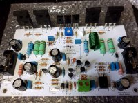
My relationship with these transistors are not from datasheet or analisis...it is real life experience..building and testing real world into my 29 degrées celsius environment...this one you see was suggested to operate with 30 volts instead of 42.....because 2 ohms operation allowed this way.
I will tell you a secret..they do not behave as the datasheet says.... datasheet was made at 25 degrées celsius..transistors operates much more hot than that.
regards,
Carlos
120W will be rms power...so..dissipation gonna be something around 200W, so, 100 Watts to each transistor aprox.
Maybe if your heatsink is really big.... infinite heatsinks.....but observe the dissipation of these transistors, watch the datasheet and check derated to 70 degrées celsius (very hot).
I do think they will not survive...but you should check if i am right or wrong.
To my amplifiers, distributed in Brazil, i have reduced the supply voltage to 30 volts for them to face 2 ohms and more than....but i was using TWO pairs.
I have not readed the entire thread...i have not time for that....but as i have faced this problem here in Brazil, with my amplifiers, i had studied the subject a lot and also i have tested and i have killed some transistors checking.
I am very sorry to be nosy.... maybe someone said different than i said..... i do not even have readed, so, i do not want to disrespect no none...i do not even know if someone have supported that or not..the use with 47 Volts or not...it looks dangerous to me...i would not do it... even to 8 and 4 ohms...too much risky...looks into the limit..if overheat a little then...Booooom!
I would like to let it clear...in my opinion SOA is not the problem, also current is not the problem...nor supply voltage either...the problem is the low capacity of these transistors to transfer heat to the heatsink..in special when overheated..... watch derated.
My relationship with these transistors are not from datasheet or analisis...it is real life experience..building and testing real world into my 29 degrées celsius environment...this one you see was suggested to operate with 30 volts instead of 42.....because 2 ohms operation allowed this way.
I will tell you a secret..they do not behave as the datasheet says.... datasheet was made at 25 degrées celsius..transistors operates much more hot than that.
regards,
Carlos
Attachments
Last edited:
Your amplifier will operate and fine, to music
As it is average..but if you insert a tone, continuous, sinusoidal, full power RMS, for some time..then you will exceed the dissipation.
You can use your amplifier for weeks....without any problem..till the day you connect a microphone and it produces feedback or a keyboard or something that produces a steady tone, full power.... then your transistors may be damaged.
Of course, if you go listen to low power.... with 47 volts or even 57 volts ..you will never face troubles.
All depends the style of test you make...i use clipping at 10 percent distortion...my amplifiers have to survive 30 minutes this way.
Others are more demanding then i am and they inject square waves...and clip the hell thing to produce a lot of harmonics.
Others are less demanding...this depends your style, your use and your needs.
Usually we do not worry about Back EMF..... but depending the phase...and when we are in the transistor limit.. output can be destroyed.
You may say.
- "Well Carlos, thread started in Jun or July.... i have assembled and it is working fine till today."
Of course i can believe on that...but if you push it hard..........one day you gonna have a surprise
regards
Carlos
Last edited:
I'm building amps for home use and listening on overdrive is extremely rare case, I don't want to destroy tweeters and ears...
Transistors that I'm lookin' for must survive not too difficult work but at maximum power that I'll compute, home amplifier insn't same as PA amplifier.
Transistors that I'm lookin' for must survive not too difficult work but at maximum power that I'll compute, home amplifier insn't same as PA amplifier.
Last edited:
driving a reactive speaker at "home" can impose more stressful demands than driving a dummy resistor load to maximum amplifier power.
The reactive stress tends to be very short term, but these short term SOAR incidents MUST be designed for.
Yes, very different from PA duty, but still very demanding and stressful.
The reactive stress tends to be very short term, but these short term SOAR incidents MUST be designed for.
Yes, very different from PA duty, but still very demanding and stressful.
It's not too uncommon to see one pair of Toshiba style output trannies used on very loose +/-60V rails in an HT receiver. They used to use one single pair of MT-200-cased Sankens up to +/-70V. Shorting the speaker output for more than a second or so with music playing or extended partying will usually kill them, but in typical domestic use with sane levels they hold up fine. A PA amplifier might use 3 pairs but rate it for use down to 2 ohms (ie, RMX1450, +/-67V, 3 pairs).
Yes...for domestic use..no problems
But as you know...people sometimes pushes the amplifier hard, in special when friends arrive to listen some music together or when they have parties.
Well..not pushing it hard..will be fine.
Mine ones, to avoid complaint, are made to be pushed hard, reason why i said:
_ Wanna use TIP35/36 folks... then reduce the voltage or looses warranty.
I have to be in the safe side..because i cannot control, remotely, user behavior nor adjust his volume knob.
You, Elektryk, can control yourself.
regards,
Carlos
Last edited:
Good protection can make miracles, when I was measuring power of old Technics amp with one pair per channel in hybrid with 57V supply, I made short circuit and relay disconnected output, nothing was burned.
So far I burned amps only during experiments, home loudspeakers anyway don't use that power (actually 6.5").
So far I burned amps only during experiments, home loudspeakers anyway don't use that power (actually 6.5").
Last edited:
Good protection can make miracles.
The chocolate coating helps it go down easier. But, you've gotta wait 15 minutes for full potency. You can short the output of a PL400 with a pair of screwdrivers while driving full output voltage - repeatedly - without damage. But get it blazing hot night after night driving two pairs of speakers at high volume, and eventually one of those times it will go up in flames.
TIP35C/36C have some good qualities - they are cheap and available from industrial components suppliers in most countries. That's where the fun stops because when you look at the SOA graph, you realise that these things are not designed to drive current over 1.5A at more than about +/-25V rails. That means you can get more power from better suited devices, despite the high peak current rating. The fact that they are rated to withstand 100V Vceo doesn't change their power capabilities from plain TIP35/36 one iota. To make matters worse, linearity is not up to audio transistor standards, though in some quarters that higher distortion may be a plus.
These are good voltage regulators or high current/low voltage switches but there are so many better transistors, cheap and suited to rail voltages up to 60V, if needed.
ON Semiconductor - datasheet pdf
These are good voltage regulators or high current/low voltage switches but there are so many better transistors, cheap and suited to rail voltages up to 60V, if needed.
ON Semiconductor - datasheet pdf
- Status
- This old topic is closed. If you want to reopen this topic, contact a moderator using the "Report Post" button.
- Home
- Amplifiers
- Solid State
- TIP35/36C maximum power at one pair