It appears that you need to fit suppressor networks across the relay switch contacts.This is usually a 0.1mFd capacitor in series with a 100 Ohm resistor.The capacitor should be rated to suit the B+ voltage with a healthy safety margin if there are filter chokes in the supply rail.
Try this.you could make me a schema
thanks
Relay contacts are conected to speakers output, short circuit in "power off", after time delay, relay is "power on" and short circuit is removed.
Need a three contacts relay.
Time delay is about 10sec. If so much, decrease R, say 470K
NEVER power up a valve amp without a load.
Attachments
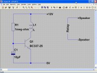
time delay
I send the schematic to see where I put the time delay or diodes
http://
I send the schematic to see where I put the time delay or diodes
http://
An externally hosted image should be here but it was not working when we last tested it.
[/IMG]
When I use damper diodes for delayed B+, I use the standard C-L-C filter for the supply hash and then add the diode and cap. This last cap becomes the Max B+ that I use to bias the output transformers. Then R-C for second stade and R-C for first stage like normal.
For the C-L-C filter be sure to use enough of a safety margine for the cap's voltage rating, stack them if you need to.
I've used this method on power amps and pre/headphone amps to prevent turn on noise, and turn on overvoltage.
For the C-L-C filter be sure to use enough of a safety margine for the cap's voltage rating, stack them if you need to.
I've used this method on power amps and pre/headphone amps to prevent turn on noise, and turn on overvoltage.
Last edited:
- Status
- This old topic is closed. If you want to reopen this topic, contact a moderator using the "Report Post" button.
- Home
- Amplifiers
- Tubes / Valves
- Time relay