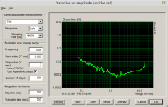
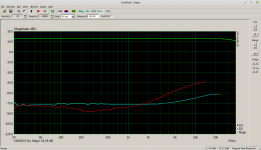
As size matters, these provide about half the saturation current than the bigger ones. They are fine for 4~8 Ohms, I would not recommend them for 2 ohms. I attach two recent test plots at 5Ohms load with these inductors. H1,2,3 vs frequency was measured at 10Vrms output (TPA3251 @30Vd supply)
Attachments
Last edited:
Though being somewhat proud of the fact that Würth, whose headquarter is just about 20 miles from here, has mutated into a very competent distributor of electronic devices (it's origin was a screw dealer...), it cannot be emphasized enough that literally any spec of any component has to be spotted on.
Best regards!
Best regards!
Input Impedance for chip pins ABCD ?
I would really appreciate some help.
What is the input impedance for pins 5, 6, 16, 17 on the 3255 CHIP ? This corresponds to inputs a,b,c,d.
I experienced terrific success upgrading the output capacitors on the TPA3255EVM running in 4 channel. I chose values based on the load impedance and the frequency range desired. I also used some better quality capacitors and the results were excellent !
!
I wish to upgrade the capacitors on the INPUT side of the 3255 chip on the 3e Audio Board.
I apologize for perhaps asking this question in the incorrect forum . Also, I have searched for the impedance before posting my query here.
Thanks in advance !
I would really appreciate some help.
What is the input impedance for pins 5, 6, 16, 17 on the 3255 CHIP ? This corresponds to inputs a,b,c,d.
I experienced terrific success upgrading the output capacitors on the TPA3255EVM running in 4 channel. I chose values based on the load impedance and the frequency range desired. I also used some better quality capacitors and the results were excellent
!I wish to upgrade the capacitors on the INPUT side of the 3255 chip on the 3e Audio Board.
I apologize for perhaps asking this question in the incorrect forum . Also, I have searched for the impedance before posting my query here.
Thanks in advance !
Link to tpa3255evm output cap swap results
I documented the output capacitor swap for the output side of the tpa3255evm here: https://www.diyaudio.com/forums/class-d/314834-ti-tpa3255evm-83.html#post5580037
I will share my sentiments when finished with the capacitor swap and testing for the input side of the 3e Audio 3255 board when finished. This will be several weeks in the future. There are several elements of the project that need work.
My initial reaction to the 3e Audio board is... good. I really like that they made the input caps in a through-hole configuration (not surface mount mini). I also really like that 3e Audio installed a socket for dip-8 opamps too. This couldn't be easier to tweak.
Sincerely,
I have 2 480w 3eaudio boards, from which I have by passed the entries stages, DAC signal directly injected to 3255 audio in without passing through the aops... Huge gain in all aspects.
Regarding the out I don't know what can be done.
I was hesitating in replacing them by 2 260w boards, to get four outputs, to bi amp my speakers, but don't know if it's possible to connect 2 3255 inputs with 1 same signal using a Y connection...
Regards
Regarding the out I don't know what can be done.
I was hesitating in replacing them by 2 260w boards, to get four outputs, to bi amp my speakers, but don't know if it's possible to connect 2 3255 inputs with 1 same signal using a Y connection...
Regards
Safety and
Thanks very much for responding! I would appreciate a sanity-check regarding my scattered thoughts below.
I suppose this is fun for me because it's new and I/we have an use for the project when finished.
With regard to the "need" for the opamp.... I suppose this is present to "help" a weak driving stage from the source (aka DAC, CD, DSP) to drive the 20k ohm input for the 3255 on pins 5, 6, 16, 17. Correct?
Many years ago I started using passive preamps in my system and have almost always found them superior to an active preamp. I believe this is because for many years the output of my Anthem CD-1 had sufficent gumption to push electrons dynamically into the 50k - 100k loads presented by various amplifiers. Interestingly , the Anthem CD-1 had a opamp buffer and dual filament tube too.
With regard to the "need" for the DC blocking capacitor.... I suppose this is present to prevent any DC current from getting into the 3255. If there was a dc blocking capacitor on the output stage of the source, this would seem sufficient. I suppose some DC could be induced in the interconnects, but this would seem unlikely. Correct ?
Thanks for reading and your response !
I have 2 480w 3eaudio boards, from which I have by passed the entries stages, DAC signal directly injected to 3255 audio in without passing through the aops... Huge gain in all aspects.
Regarding the out I don't know what can be done.
Thanks very much for responding! I would appreciate a sanity-check regarding my scattered thoughts below.
I suppose this is fun for me because it's new and I/we have an use for the project when finished.
With regard to the "need" for the opamp.... I suppose this is present to "help" a weak driving stage from the source (aka DAC, CD, DSP) to drive the 20k ohm input for the 3255 on pins 5, 6, 16, 17. Correct?
Many years ago I started using passive preamps in my system and have almost always found them superior to an active preamp. I believe this is because for many years the output of my Anthem CD-1 had sufficent gumption to push electrons dynamically into the 50k - 100k loads presented by various amplifiers. Interestingly , the Anthem CD-1 had a opamp buffer and dual filament tube too.
With regard to the "need" for the DC blocking capacitor.... I suppose this is present to prevent any DC current from getting into the 3255. If there was a dc blocking capacitor on the output stage of the source, this would seem sufficient. I suppose some DC could be induced in the interconnects, but this would seem unlikely. Correct ?
Thanks for reading and your response !
I have made more progress . This new FFT was made after optimizing zobel network . Instead of one cap and one R I used 3 caps in parallel with 3 R in parallel . THD is 0.00045
Note also the absence of H3 . Basically there is no change between 100Hz and 6.67Khz (rise is almost null )
Notice also the lack of H5 -H20
I think that at this point this is the best measured TPA3255 (at 5W , 1Khz , 8R)
Note also the absence of H3 . Basically there is no change between 100Hz and 6.67Khz (rise is almost null )
Notice also the lack of H5 -H20
I think that at this point this is the best measured TPA3255 (at 5W , 1Khz , 8R)
Attachments
Do tell, which thread... a link ?
This one, I believe:
TPA3255 - all about DIY, Discussion, Design etc.
Might work
I don't directly know the answer, but I have tried ADDING capacitance to the power supply input rails. There was no sonic change or improvement - at least to my ears. // I was NOT using the board for running subwoofers at maximum value. This would probably be a more "needy" load.
Maybe this helps somewhat.
I'm just trying to use a single SMPS to power multiple amps and I'm getting lots of input that there's a significant risk of it not working due to the excessive output capacitance. The EVMs have 9.4 mF each and the SMPS I have supposedly doesn't like 6-8 mF output capacitance. Two EVMs together would be way over, but I'm willing to take the chance if they had 2x 2200 uF each.
- Home
- Amplifiers
- Class D
- TI TPA3255EVM