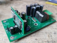
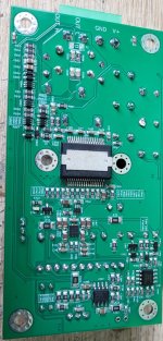
I need to ask this question because it appears to be unexplored.
Why does the amplifier have an adjustable frequency? In my recent simulations, I observed that randomly sweeping frequencies—or in your case, toggling between two frequencies—significantly influences the "system's overall transfer response" control theory domain. By selecting an "idle target frequency" and designing the poles and zeros around this point for different operational states, the "final set point idle frequency" is established. However, this necessitates readjusting the LC double pole at the output. Given these complexities, I'm curious why these frequency sweeps are conducted as a production "user settable" option, as they seem to complicate the predicted behavior of the control loop.
Why does the amplifier have an adjustable frequency? In my recent simulations, I observed that randomly sweeping frequencies—or in your case, toggling between two frequencies—significantly influences the "system's overall transfer response" control theory domain. By selecting an "idle target frequency" and designing the poles and zeros around this point for different operational states, the "final set point idle frequency" is established. However, this necessitates readjusting the LC double pole at the output. Given these complexities, I'm curious why these frequency sweeps are conducted as a production "user settable" option, as they seem to complicate the predicted behavior of the control loop.
In this case, I didn't notice an impact in the audio range.
The frequency boost option activates the feedback before the filter, as it is realized in the original ET400 modules.
But since the delay in my circuit is much lower than in the ET 400, even without the additional boosting OS, the frequency is 600-640kHz
The frequency boost option activates the feedback before the filter, as it is realized in the original ET400 modules.
But since the delay in my circuit is much lower than in the ET 400, even without the additional boosting OS, the frequency is 600-640kHz
Interesting, I think the influence of the loop are during "modes" and NOT audiophile listening evaluation.
I read the paper and noticed some areas of interest like clip recovery and current trip under operations such as loud playback or even shorting the output.
- 600-640kHz I cannot seem to get an IRS20957 (due an already internal 350ns delay + 10ns comp delay) using an NCORE modulator to go that high, not without 100p/220p lead/lag networks, I don't like 10^-9 pico farad values in loops they seem to be sensitive to finger touching drift.
Sorry I had some doubts on the figure you supplied, where did you get 140ns? I had a look at the datasheet for the IRS20957 and here are the exact figures.IRS20957 latency is about 140ns with switches and comparator.
Updated for Minimum, Typical and Maximum.
Minimum Delay Calculation:
- Turn-on rise time (tr): 15 ns
- Turn-off fall time (tf): 10 ns
- Turn-on propagation delay (Ton1): 95 ns
- Turn-off propagation delay (Toff1): 80 ns
- Minimum deadtime (DT1_min): 8 ns
tp1_min = Ton1 + tr + DT1_min + Toff1 + tf
tp1_min = 95 ns + 15 ns + 8 ns + 80 ns + 10 ns = 208 ns
For non-floating inputs:
tp2_min = Ton2 + tr + DT1_min + Toff2 + tf
tp2_min = 95 ns + 15 ns + 8 ns + 80 ns + 10 ns = 208 ns
Typical Delay Calculation
- - Turn-on rise time (tr): 15 ns
- - Turn-off fall time (tf): 10 ns
- - Turn-on propagation delay (Ton1): 95 ns
- - Turn-off propagation delay (Toff1): 80 ns
- - Typical deadtime (DT1_typ): 15 ns
For floating inputs:
tp1_typ = Ton1 + tr + DT1_typ + Toff1 + tf
tp1_typ = 95 ns + 15 ns + 15 ns + 80 ns + 10 ns = 215 ns
For non-floating inputs:
tp2_typ = Ton2 + tr + DT1_typ + Toff2 + tf
tp2_typ = 95 ns + 15 ns + 15 ns + 80 ns + 10 ns = 215 ns
Maximum Delay Calculation:
- Turn-on rise time (tr): 15 ns
- Turn-off fall time (tf): 10 ns
- Turn-on propagation delay (Ton1): 95 ns
- Turn-off propagation delay (Toff1): 80 ns
- Maximum deadtime (DT1_max): 22 ns
For floating inputs:
tp1_max = Ton1 + tr + DT1_max + Toff1 + tf
tp1_max = 95 ns + 15 ns + 22 ns + 80 ns + 10 ns = 222 ns
For non-floating inputs:
tp2_max = Ton2 + tr + DT1_max + Toff2 + tf
tp2_max = 95 ns + 15 ns + 22 ns + 80 ns + 10 ns = 222 ns
Total Minimum Delay: 208 ns
Total Typical Delay: 215 ns
Total Maximum Delay: 222 ns
Attachments
Last edited:
- Home
- Amplifiers
- Class D
- TI power stage for selfoscillating amplifier


