For 30V you will have to adjust R4/R104 to somewhere between 12.75K to 13K. The proto's have 12.76K on the positive side and 13K on the negative side. So prepare for a little tweaking if you want excact values on the rails. Trimpots were used to arrive at those values. The boards has provision for 2 pcs // R4's and r104's to make it easier to do odd values.
")

Guido and all,
The etch file for the Toole shuntreg is bigger than allowed to post on this forum so anyone interested on it please PM me and let me know if you need a cooper or component side view for your transfer process. The files are available in pdf; no gerber’s have been done.
The etch file for the Toole shuntreg is bigger than allowed to post on this forum so anyone interested on it please PM me and let me know if you need a cooper or component side view for your transfer process. The files are available in pdf; no gerber’s have been done.
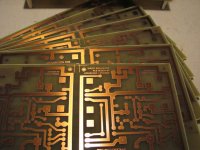
This is what the boards look like
Apassgear did a tremendous job on those boards. The etch file is very DIY userfriendly!
The Toolereg doesnt run overly hot! It is pretty easy on the heatsinking! Ofcourse it depends on the settings made by the user, but if the general recommendations are followed, only small heatsinks are needed.
Apassgear did a tremendous job on those boards. The etch file is very DIY userfriendly!
The Toolereg doesnt run overly hot! It is pretty easy on the heatsinking! Ofcourse it depends on the settings made by the user, but if the general recommendations are followed, only small heatsinks are needed.
Attachments
Etch file for the Toole Suntreg
To all who requested etch files for the Toole reg I have sent a layout file with both positive and negative components for you to follow through the construction, makes it easier.
The other file contains the artwork for transferring to your board, there is one seen from the component side and another from the copper side for you to select the appropriate one according to the system you will be using. Make sure that it prints to scale.
Please let us know thru the forum on your outcome and what you think about this project.
Steen,
Those PCB's really look great. The process your following has an excellent resolution I can even read the lettering thru the pic you posted.
I might even be doing a compact size artwork for the Toole reg for you to test, I remember those you did for the NS10 which had thinner traces and they came out fantastic too.
Toole shuntreg
All etch files and layouts requests until yesterday have been sent.
Please remember that positive and negative reg polarities are built using the same PCB and that instructions for setting the regs are shown on the schematic file.
Please direct all questions you may have thru this thread so everyone is benefit with your experience.
Cheers
Setting the regulators is an easy task if you know what to do. In the other hand fortunately the circuit is very stable with no tendencies for oscillation if you build it as proposed.
For those of you who is the first time fiddling with a shunt regulator I will prepare some tips for setting it up and what you have to look for to have it working properly… so no fear.
For those of you who is the first time fiddling with a shunt regulator I will prepare some tips for setting it up and what you have to look for to have it working properly… so no fear.
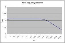
Measuring the NS10-clone with a 5pF compensation cap, was pretty interesting, but not surprising.
The Frequency response is now absolutely flat to over 200kHz, dropping from there, caused by the the cap. Comparing to the plot without a compensation cap, shows that the very slight bump at 20kHz-100kHz is gone, and substituted by a general descent from 200kHz.
Well, I cant say that I can hear any difference between the two, so take your pick
Here is the plot with the 5pF in place, using the same Y-scale as the last dB plot.
Attachments
steenoe said:Measuring the NS10-clone .....
anyway - I'm starting to worry about you ....... recently you started to measure .......
Zen Mod said:
anyway - I'm starting to worry about you ....... recently you started to measure .......
Yeah, I cant blame you
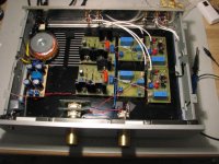
No need to worry though, I am just fine. I guess that curiosity got me. Still being reckless, I hit every circuit around, with 220V AC The only thing that bothers me, is the USD currency rocketing again! It is starting to cost mucho dinero to import from the states ( read Digikey )Anyway, here is a shot of the singleended preamp so far. I am still trying to figure out how to do the switching between the B1 and the NS10 with minimal lead length's. Maybe i will just stick with internal switching as it has now. As you can see, I have made 2 sets of output's. The flying input leads are for the purpose of changing between buffer/gainstage...
It is all just temporary, but if you have a really clever idea for switching between the two..... I am all ears... Ofcourse I have thought of moving the input selector/volumepot to the rear.
BTW, NP the clever guy, is a copycat! I just read that the XP preamps has switchable buffer/gainstage....
It is all just temporary, but if you have a really clever idea for switching between the two..... I am all ears... Ofcourse I have thought of moving the input selector/volumepot to the rear.
BTW, NP the clever guy, is a copycat! I just read that the XP preamps has switchable buffer/gainstage....
Attachments
Steen,
That’s an impressive build and excellent work that we all seem to expect from you but few can match for sure. That plot looks also fantastic the BW is still impressive even with the compensation cap showing a -1dB at 2MHz!
We are now needing a shootout between the clever guy’s XP and Steen’s NS10 + B1 buffer preamp
Wonder what Nelson would think today of this updated NS10 clone.
- Status
- This old topic is closed. If you want to reopen this topic, contact a moderator using the "Report Post" button.
- Home
- Amplifiers
- Pass Labs
- Threshold NS10 Lineamp PCB