Fo safety reasons the transformer casing should not be isolated from the safety earth. However, if the fixing bolts pass through the laminations (if it's a drop-through style of mounting) then it may be that you should put fibre washers under three of the heads so that they do not combine to create paths for induced currents. One of the bolts must remain with a fully conductive path, however.Given that it higher closer to the transformer . I would stainless steel bolts and some washers and get the tranny off of the chassis . Teflon , polyprop, rubber or fiber will work . My guess is the the frame of the tranny is inductively coupling to the chassis distance and non magnetic (stainless steel ) or brass bolt will help.
no switching power supply. classic full wave cetner tapped rectified with 4n1007 diodes. i've done both little and lots of filtering with no change. tried .1uf bypass caps on c
the noise, which i'd describe as a hum/buzz (so, 60hz with lots of harmonics), is the *same* throughout the original post, to clarify.
so, the o'scope puzzle, eh? here are my troubleshootings about *that*...
1) doesn't happen with any other electronics on my bench. period. never has. so, if it is something that is just 'seen' with the scope, then something in this chassis itself is causing a ground loop.
2) i've also done scope probes with and without the scope probe 'ground' clip on the chassis. all that does is clear up some 'fuzz' i see on any probed signal. you know, this is just kinda standard scope procedure. but, to note, i've worked the scope with ground clip to chassis (or star ground) to no difference (other than a little clarity on the waveform)
3) the 'look' of the waveform produced by the probe when hovered close to/near the power transformer is very similar to the noise that i'm seeing after amplification. when i'm using a large power transformer, i can clearly see about the same waveform on the chassis being conducted. when using a smaller voltage power transformer, i see a very small but similar waveform ripple on the chassis. my rationale, so far, is that since I'm doing more R-C stages and voltage knockdown with the bigger transformer, more current is being used and such the chassis current is higher.
scope is a tek 465, btw. i've done (and still do) great troubleshooting with that thing.
so, let's say, for argument's sake, that I don't have a scope, or that my thought that I'm seeing a 'noisy' ground is inaccurate.
my b+ is filtered very nicely. 68uf after rectifier, 20H choke + 100uf, 4.7k + 100uf (this feeds the 6fq7 CF's and ef86's), then 2.2k + 220uf (to feed 6sj7 input stages).
i have not tried running DC to filaments. i've relooked and re-twisted/tried new layouts for the AC twisted filament wires. the filaments go to the 6fq7 first, then each ef86, then each 6sj7, one at a time, in parallel, of course. however, i've read and deduced that filament hum would be seen as (mostly) pure 60hz, no? and not quite this mangled hum/buzz i'm experiencing. would anyone suggest i try DC for filaments? it's one of the only things i haven't tried. however, my test i noted to turn off the filament line to the tubes (as b+ is still active) for just a few seconds while the tubes are still conducting yielded no reduction to the hum/noise, so this led me to feel that a filament AC problem is not what's causing this.
thanks for the thought help, everyone, so far. i'd like to solve this and add it to the knowledge database here!
i'll try to get some pics in the next few days. i'm moving cross country on friday...
The basic thing really comes down to a few points:
A. In any high gain amp, mixer, the filaments are DC in the preamp---think about it...any AC field that enters the audio path is amplified.
That's why the best tube hi fi amps had DC heaters for the preamp stages. Look at the Macintosh Schematics for hi fi pre-
amps. You can find all types of DC power supply circuits for your filaments.
It is not unusual to install 10,000 uF caps in the filament supply. the goal is to eliminate all the ripple, and I mean every single Milli volt.
B. The unused inputs must be grounded, or turned down to zero.
You must have a microphone connected, or the input should be grounded, to determine the actual noise level. An unterminated input "will" hum.
C. The power supply is grounded on one side of the chassis. The audio circuit is grounded on the other side of the chassis.
It may seem like a star ground is the best solution...but not really. You really need the power supply to be removed from the preamp ground.
Between the power supply ground and the preamp ground, there is the resistance of the chassis.
believe it or not, this small resistance actually decreases the hum! (you would be surprised)
The power supply filters are dumping rejected 60 cycle ripple, and it turns out that the preamp ground is best "removed" from this vicinity.
D. Never underestimate the noise from components like disk capacitors. These components absorb the 60 cycle field from the filaments, and inject this noise directly into the audio path. AND that noise is amplified.
Using silver mica instead in the first gain stages can make on heck of a difference.
E. 60 cycle noise can also be the result of high frequency oscillation in the preamp. You need a good scope to observe this.
DC heaters may eventually be necessary to get rid of the last traces of hum, but I doubt if the heaters are the main problem. All the evidence points to ground currents. Can you measure the capacitance between the primary winding and the transformer frame? Swapping live/neutral (or whatever it is called over there) might help if one end of the winding has higher capacitance than the other.
I don't understand the comment about disk capacitors 'absorbing the 60 cycle field from the filaments'. Ceramic caps can be piezoelectric so respond to acoustic fields or vibration, but I'm not aware of any particular propensity to 'absorb' electric or magnetic fields any more than any other cap.
Yes, RF oscillation could be the problem although I would not expect that to show up as 60Hz on the chassis.
DC heaters may eventually be necessary to get rid of the last traces of hum, but I doubt if the heaters are the main problem. All the evidence points to ground currents. Can you measure the capacitance between the primary winding and the transformer frame? Swapping live/neutral (or whatever it is called over there) might help if one end of the winding has higher capacitance than the other.
I don't understand the comment about disk capacitors 'absorbing the 60 cycle field from the filaments'. Ceramic caps can be piezoelectric so respond to acoustic fields or vibration, but I'm not aware of any particular propensity to 'absorb' electric or magnetic fields any more than any other cap.
Yes, RF oscillation could be the problem although I would not expect that to show up as 60Hz on the chassis.
Measure the 60 cycle on your output...
now measure the 60 cycle with DC heaters attached...
It is not usually "one" source of hum, it's several sources added together...
Components act like antennas. A capacitor, at certain frequencies, can be an inductor.
Last edited:
C. The power supply is grounded on one side of the chassis. The audio circuit is grounded on the other side of the chassis.
...so chassis is in the ground loop when other equipment is connected. Congratulations.
You still need to fix the signal and signal ground separation problem. The signal ground paths need to be right against the signal paths, all the way across your schematic. The cathode ground and grid ground and and everything connected to them need to hug right against the the grid input signal path and the cathode to ground path. The grid input ground and cathode ground for each tube should be at the same place, probably at the cathode ground. Refering to the schematic, those will be the only grounds down at that level, There won't be any ground dropping down from a pot, for example, because they will go left and right from each pot, to follow the signal path. From each cathode ground, a wire will go up to the anode and follow the signal wire to the next tube's grid and then down to the cathode ground, along with the grid resistor and its ground connection path.
If you want to run the single signal ground associated with the first tube as a separate run to the star ground, you can, if you break the ground connection that goes from there to where it follows the next tube's input signal path. But if you decide to leave the three together, then just run a single wire to the star ground from the first tube's ground, rather than from anywhere to the right of that.
It only makes sense for the star ground to be after the last smoothing cap's ground (i.e. farther from the transformer). The cap-charging current spikes go from the secondary(s) through the rectifier and the smoothing caps and back to the center tap. You don't want the star ground in that loop. As DF96 said in another thread, put the ground at the output of the power supply.
The secondary and center tap wires should be twisted all the way to the rectifier and then from there all the way to the first smoothing cap's pins. If using wires to connect + and - pins of adjacent smoothing caps, twist them together all the way from cap to cap. (Always try to get four or more turns per inch.)
The grounds for any other caps that connect to the supply rail should follow those connections and that rail all the way back to the star ground. (Power and power ground should stay together, everywhere, just like signal and signal ground.)
Shouldn't the "bias grid" cap grounds be part of the power supply grounding, rather than the ss grounding?
Last edited:
first: update regarding power supply bolt and lam isolation:
first, electrically removed it from the chassis. no change. just one bolt; no change. all four; no change. having some rubber washers on each side definitely has dampened the slight mechanical buzz from the power tx, though. so, that was nice.
anyways, onward!
ok, pardon my asking: why is it important to have them next to each other like so? is it enclosed loop area we're talking about here? i have all main signal leads shielded and connected to ground (read past posts regarding details and trials of such), and relocating other active runs (cathode, screen, etc) closer to or further away from the chassis hasn't made any difference in amplified hum levels. i'll take the extra precautions and start doing this, though. yet, as they are, they're close, and moving them closer/further away from any other run, both signal OR ground, hasn't made a difference I could see. yet, I haven't done a tight wrap of such; but, i'll give it a go. good thought.
need to clarify; not sure what you're talking about here. sorry. right now i have it connected as such for the first stage...
input grid resistor bottom -----> screen grid bypass cap bottom ---- > cathode cap/resistor bottom ----- > to star ground
the arrows are all rather short connections and are in a physical straight line.
i previously had individual runs from each going to star ground - this configuration was much less noisy. cut it in half. most possibly due to the reduction of different ground wires travelling to star, and hence less loop areas...
is this in agreement with what you were saying?
all of that makes total sense. i'll go through the extra precautions.
power supply related observation: the noise on the B+ rail is higher after my 4th filter stage (which supplies the 1st gain stage) than the 3rd filter stage (which supplies the 2nd gain stage and CF output). i'll re-look at the grounding more critically per your post; thoughts on this, though?
something i JUST considered when thinking of cap filtering RC networks is phase of current filtering...
i'll try it.
first, electrically removed it from the chassis. no change. just one bolt; no change. all four; no change. having some rubber washers on each side definitely has dampened the slight mechanical buzz from the power tx, though. so, that was nice.
anyways, onward!
You still need to fix the signal and signal ground separation problem. The signal ground paths need to be right against the signal paths, all the way across your schematic. The cathode ground and grid ground and and everything connected to them need to hug right against the the grid input signal path and the cathode to ground path. The grid input ground and cathode ground for each tube should be at the same place, probably at the cathode ground. Refering to the schematic, those will be the only grounds down at that level, There won't be any ground dropping down from a pot, for example, because they will go left and right from each pot, to follow the signal path. From each cathode ground, a wire will go up to the anode and follow the signal wire to the next tube's grid and then down to the cathode ground, along with the grid resistor and its ground connection path.
ok, pardon my asking: why is it important to have them next to each other like so? is it enclosed loop area we're talking about here? i have all main signal leads shielded and connected to ground (read past posts regarding details and trials of such), and relocating other active runs (cathode, screen, etc) closer to or further away from the chassis hasn't made any difference in amplified hum levels. i'll take the extra precautions and start doing this, though. yet, as they are, they're close, and moving them closer/further away from any other run, both signal OR ground, hasn't made a difference I could see. yet, I haven't done a tight wrap of such; but, i'll give it a go. good thought.
If you want to run the single signal ground associated with the first tube as a separate run to the star ground, you can, if you break the ground connection that goes from there to where it follows the next tube's input signal path. But if you decide to leave the three together, then just run a single wire to the star ground from the first tube's ground, rather than from anywhere to the right of that.
need to clarify; not sure what you're talking about here. sorry. right now i have it connected as such for the first stage...
input grid resistor bottom -----> screen grid bypass cap bottom ---- > cathode cap/resistor bottom ----- > to star ground
the arrows are all rather short connections and are in a physical straight line.
i previously had individual runs from each going to star ground - this configuration was much less noisy. cut it in half. most possibly due to the reduction of different ground wires travelling to star, and hence less loop areas...
is this in agreement with what you were saying?
It only makes sense for the star ground to be after the last smoothing cap's ground (i.e. farther from the transformer). The cap-charging current spikes go from the secondary(s) through the rectifier and the smoothing caps and back to the center tap. You don't want the star ground in that loop. As DF96 said in another thread, put the ground at the output of the power supply.
The secondary and center tap wires should be twisted all the way to the rectifier and then from there all the way to the first smoothing cap's pins. If using wires to connect + and - pins of adjacent smoothing caps, twist them together all the way from cap to cap. (Always try to get four or more turns per inch.)
The grounds for any other caps that connect to the supply rail should follow those connections and that rail all the way back to the star ground. (Power and power ground should stay together, everywhere, just like signal and signal ground.)
all of that makes total sense. i'll go through the extra precautions.
power supply related observation: the noise on the B+ rail is higher after my 4th filter stage (which supplies the 1st gain stage) than the 3rd filter stage (which supplies the 2nd gain stage and CF output). i'll re-look at the grounding more critically per your post; thoughts on this, though?
something i JUST considered when thinking of cap filtering RC networks is phase of current filtering...
Shouldn't the "bias grid" cap grounds be part of the power supply grounding, rather than the ss grounding?
i'll try it.
Many people find distributed star grounding is easier to apply, and fundamentally better for valve amp stages. Merlin describes it well:
The Valve Wizard
The Valve Wizard
Seems to confirm that you have a grounding problem.themagicmanmdt said:power supply related observation: the noise on the B+ rail is higher after my 4th filter stage (which supplies the 1st gain stage) than the 3rd filter stage (which supplies the 2nd gain stage and CF output). i'll re-look at the grounding more critically per your post; thoughts on this, though?
just solved most of it...
first, changed the grounding scheme to what DF96/gootee had mentioned. this was the quietest solution I've tried! this helped the ground noise seen on the last cap, too. to further mention: i soldered the secondary CT right at the negative terminal at the cap (I mean...RIGHT at it!) along with the heater CT; this was also the quietest config i've tried.
further, i found the hum was also reduced by NOT terminating the secondary of the transformer with a 220k resistor to 'test'. i decided to hook up the mic leads to the XLR, and in doing so, unterminated the 22k resistor. the hum reduced equally as much as the power supply update mentioned above. terminating the secondary with a fixed load only creates more hum. the reflected impedance through the transformer seems to be fine, as well as amazingly quiet.
third; read the sticky regarding heater wiring, and decided to get anal with it and give them all a few more twists.
fourth; having the lid on and the mic at least 1' away from the preamp was also significant.
so, now, with the full ~80db of gain, i'm getting a S/N of at least 80db; and even better when running the EF86 as triode (although less gain; i have the ef86 on a pentode/triode switch); it's more than quiet enough for my ribbon mics for vocals in a room, ala 'smiley smile'")
thanks for the help, everyone. i'll follow up as I continue to further chase down s/n reduction and that 'teeny' bit of hum left when it's running wide open. yet, i'll call it 'solved':
so, here, to recap, were all the things that ended up helping:
*power supply in a separate star than signal ground
*power supply star is connected with the sec. center tap and heater center tap very very close to the first filter cap pair twist (as close to the neg terminal as possible); then all filter caps, one at a time, with the connection to chassis ground after the last filter cap
*signal star connected with lowest current draw sections furthest from chassis ground on a small 'buss', with the highest current drawing sections closest to the star chassis ground connection
*grouping each stage in a 'sub-star' connection B/C the less long leads and 'loop' area between grounds, the better;
*twist ground leads going back to signal star connection if possible, just like a heater lead
*be careful when 'test-terminating' a transformer; it seem to create a small loop by terminating it on the transformer pins (solder-type, that is) - I used UTC O-8 inputs wired 1:10.
*use shielded signal cables, and terminate the shield on the side where the signal is originating, not terminating (ex: from plate blocking cap to volume pot; terminate the shield at the cathode of the tube it 'came from')
*isolating the power transformer with rubber washers helps remove mechanical hum.
that's all off the top of my head
anyone have further thoughts?
thanks; hopefully this is a good thread for the vault
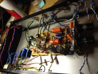
oh look, here's a picture (hahahahahaha)
now, to have a variable NFB control and make it pretty.
now, time for me to help a bit, if i can, for everyone else...
much love.
first, changed the grounding scheme to what DF96/gootee had mentioned. this was the quietest solution I've tried! this helped the ground noise seen on the last cap, too. to further mention: i soldered the secondary CT right at the negative terminal at the cap (I mean...RIGHT at it!) along with the heater CT; this was also the quietest config i've tried.
further, i found the hum was also reduced by NOT terminating the secondary of the transformer with a 220k resistor to 'test'. i decided to hook up the mic leads to the XLR, and in doing so, unterminated the 22k resistor. the hum reduced equally as much as the power supply update mentioned above. terminating the secondary with a fixed load only creates more hum. the reflected impedance through the transformer seems to be fine, as well as amazingly quiet.
third; read the sticky regarding heater wiring, and decided to get anal with it and give them all a few more twists.
fourth; having the lid on and the mic at least 1' away from the preamp was also significant.
so, now, with the full ~80db of gain, i'm getting a S/N of at least 80db; and even better when running the EF86 as triode (although less gain; i have the ef86 on a pentode/triode switch); it's more than quiet enough for my ribbon mics for vocals in a room, ala 'smiley smile'
thanks for the help, everyone. i'll follow up as I continue to further chase down s/n reduction and that 'teeny' bit of hum left when it's running wide open. yet, i'll call it 'solved':
so, here, to recap, were all the things that ended up helping:
*power supply in a separate star than signal ground
*power supply star is connected with the sec. center tap and heater center tap very very close to the first filter cap pair twist (as close to the neg terminal as possible); then all filter caps, one at a time, with the connection to chassis ground after the last filter cap
*signal star connected with lowest current draw sections furthest from chassis ground on a small 'buss', with the highest current drawing sections closest to the star chassis ground connection
*grouping each stage in a 'sub-star' connection B/C the less long leads and 'loop' area between grounds, the better;
*twist ground leads going back to signal star connection if possible, just like a heater lead
*be careful when 'test-terminating' a transformer; it seem to create a small loop by terminating it on the transformer pins (solder-type, that is) - I used UTC O-8 inputs wired 1:10.
*use shielded signal cables, and terminate the shield on the side where the signal is originating, not terminating (ex: from plate blocking cap to volume pot; terminate the shield at the cathode of the tube it 'came from')
*isolating the power transformer with rubber washers helps remove mechanical hum.
that's all off the top of my head
anyone have further thoughts?
thanks; hopefully this is a good thread for the vault
oh look, here's a picture (hahahahahaha)
now, to have a variable NFB control and make it pretty.
now, time for me to help a bit, if i can, for everyone else...
much love.
Attachments
Strange, lots of people find this! Maybe because it is actually correct, but people seem reluctant at first to believe that such a simple change can make so much difference. Unlike some tweaks, this one is based on sound science like Ohm's Law.first, changed the grounding scheme to what DF96/gootee had mentioned. this was the quietest solution I've tried!
Keep charging pulses in a tight loop well away from the signal ground.
similar to my warning shot fired off in December 2004 where I clearly state that keeping the pulse of the charge currents away from the audio ground.
I see that users are still basing their grounding scheme on the post 143 diagram.
I strongly suggest you DO NOT use multiple grounding as shown on this diagram!!!!
The peak / pulse currents flowing between the capacitors through this plate will contaminate your audio signal.
If you insist on using the cap common as your clean and dirty ground then use the Sugden trick:- put a brass ( or better still a copper) bolt through the plate and nut it up firmly. Connect all your clean and dirty grounds to the other side of the nut, then they are isolated from the pulse currents between the caps. or connect a single wire from the cap common to a remote audio star ground.
I suspect that when people read 'copper is a good conductor' what they think is 'copper is an infinitely good conductor' so they then believe that any points connected by copper must be at the same potential. Spice reinforces this misunderstanding, so it confuses newbies.
When designing power supples and output stages it would be better for people to understand that copper wires (however 'oxygen-free') are resistors, albeit fairly low value resistors.
When designing power supples and output stages it would be better for people to understand that copper wires (however 'oxygen-free') are resistors, albeit fairly low value resistors.
When designing power supplies and output stages it would be better for people to understand that copper wires (however 'oxygen-free') are resistors, albeit fairly low value resistors.
...And (although mostly off-topic for this forum) for switching power supplies and for any digital electronics, even short lengths of copper can have enough inductance to have a big effect on signal integrity.
- Status
- This old topic is closed. If you want to reopen this topic, contact a moderator using the "Report Post" button.
- Home
- Amplifiers
- Tubes / Valves
- Thoughts of apparent noise on ground - due to power tx?