Ok, I give up, almost. I have built a PPP6080 amp and am having difficulty getting even 20 watts out of it. According to what I see in the tube specs PPP should proved 20 to 24. 210 volts plate supply from a 2A toroid and 1,100 ufd input cap, and combo fixed and cathode bias. The issue seems to be that I can not get enough signal out of the drivers (6GU7s). One 6GU7 (two triodes) in cascode driving 2 paralleled grids can deliver about 140V pp of clean drive. However the bias for AB2 is about -95 volts. The available B+ for the drivers is 400 volts. Everything tells me I should be able to get at least half (200) of the B+ voltage as a PP signal swing out of the two 6GU7 sections in cascode.
WHats wrong with my thinking here? Any and all thoughts will be appreciated.
WHats wrong with my thinking here? Any and all thoughts will be appreciated.
In my class AB2 PPP 6080 amp breadboard, I believe I clocked about 70mA of grid current from the drivers on signal peaks at 28W output, using an OPT with 1KCT primary. Output stage gain was very close to unity. What are you doing to handle the grid current? How about posting the schematic?
Assuming you have correct bias, if your not loading your 6GU7's correctly you will not swing volts...
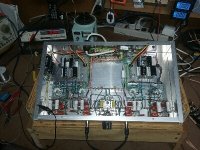
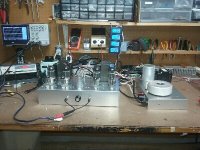
So I agree with Mike. Please post your schematic and take some pictures of your work. Post them here by using the "Go Advanced" reply.
Also, it might be useful to explain how you are measuring output, what sort of speakers you are using, etc.
So I agree with Mike. Please post your schematic and take some pictures of your work. Post them here by using the "Go Advanced" reply.
Also, it might be useful to explain how you are measuring output, what sort of speakers you are using, etc.
Last edited:
Pesky Triodes2
I really dont have a complete schematic. 70 mills of grid current...wow. Wouldn't you have to have something like a 6L6 driving them? I'd like to go higher on the driver B+ but I am afraid the top tube would short HK. Franly I havent done much with radio transmitters where I hear tubes normally draw grid current. Another difference is my OT is a 50W 2K ct but I am running the 16 tap with 8 load to reduce the output tube impedence with all four triode sections working I can get barely 10 watts. THey are very nice sounding watts though.
The only thing I tried to do in the drivers is keep the plate resistor as low as possible 47K . Its strictly a RC coupled VA then A balance PI cap coupled to a 6GU7 in cascode then cap coupled to each side the 6080s. I'll work on some kind of a schematic but I just finished the change to that cascode driver today and its only in my mind...scarey place.
would you care to tell me why. Dont have that problems with pentodes....and cap coupling ain't gonna work for AB2.
You are telling me that the grid in that ube is drawing current like a transistor Base?If you're running AB2, you need current. Lots of current from a low impedance. A source follower is not a bad idea there, driving it with a cathode follower will likely yield lower performance..
Pictures are posted, I dont know what happened to the PDF for the schematic. Standard testing for output. 8 ohm load. AUdio dual pointer RMS voltmeter. volts (squared) divided by resistance.Assuming you have correct bias, if your not loading your 6GU7's correctly you will not swing volts...
So I agree with Mike. Please post your schematic and take some pictures of your work. Post them here by using the "Go Advanced" reply.
Also, it might be useful to explain how you are measuring output, what sort of speakers you are using, etc.
would you care to tell me why. Dont have that problems with pentodes.
Because the grid starts drawing current like the base of a transistor. It will charge the coupling cap and throw off bias toward cutoff, causing "blocking distortion".
With most common load lines, pentodes can be driven to saturation with negative grid voltages and the grid does not draw current. Are you certain you were operating AB2 and not AB1, which draws no grid current?
ETA: Just looked at the schematics and your amp will clip at Vg=0. You need a direct-coupled follower or interstage transformer to drive the grids positive. Once the grid reaches positive voltages (with respect to the cathode) it will start attracting electrons and there is current flow.
Last edited:
You are telling me that the grid in that ube is drawing current like a transistor Base?
Yeah, pretty much like that. For full-on class AB2 your driver should reach perhaps +20V peak, which puts your total drive requirement at 230Vpp. It has to be DC-coupled, and it has to drive the grids positive without distorting as it transitions into the grid current region. It's a difficult set of requirements that is often met by a MOSFET source follower or Sziklai pair of transistors these days. Cathode followers and interstage transformers were standard solutions in the past, but didn't work as well because of greater source impedance.
Are you sure that the drawing of the output stage is correct? According to your drawings, you are driving two output triodes in parallel with each phase of the drivers but the anodes of these triodes are cross-connected to the output xfrmer - if this is the case, the output signal will cancel each other! The only ac signal the transformer sees would be the imbalance of the triodes.
Another thing to be aware of when designing amps like this: Anode voltage on the side of the push-pull output stage that's in cutoff will swing close to 350V, which can easily cause the tubes to start conducting if your driver doesn't push the grids adequately negative. In other words, don't think that your driver design can be simplified by allowing it to compress negative peaks because that distortion won't appear in the output signal!
Exactly this. In circuit, and in tube tester is not the same.6080's generally produce unity gain in the output stage.
Shoog
Funny how people are surprised, why ecc83 has way less than 100x gain. "Not possible ! Datasheet said µ=100 !!!!"

I don't think the current design even gets into the voltage range where grid current flows, very simply the driver stage needs to be able to swing to the point where grid current flows for class AB2 operation to be a consideration. Currently the driver cannot drive the grids to within 20V of the transition to class AB2 operation.
Getting to the point where you can drive the grids to close to 0V should be the first goal, if at that point more power is still required you can aim for more drive and the current required for AB2.
As an aside comment cascode amplifier circuits are not the efficient choice where large swings are required on a reasonable supply rail.
I'd recommend a single triode per phase driving a center tapped choke for PP drive. You'll easily make 400Vpp (unloaded) with the 6GU7 using such a strategy.
aboos is right!
According to both of the schematics, the phases of the plates are cancelling.
You have 1 in phase plate driving the top of the secondary, and 1 plate out of phase driving the bottom of the secondary. Then you have a second out of phase plate driving the top of the secondary, and a second in phase plate driving the bottom of the secondary.
All you can get out that way is the imbalance of the 4 output triodes.
- Status
- This old topic is closed. If you want to reopen this topic, contact a moderator using the "Report Post" button.
- Home
- Amplifiers
- Tubes / Valves
- Those Pesky triodes