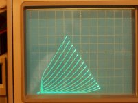
I fixed the offset on the last set of 6P41S curves above (180K, 15K, 2.5V steps) to give a better view of linearity change (less) with higher Mu.
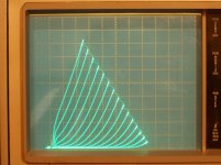
a) UnSET 6P41S Curves 180K, 30K, 4V steps, 190V grid 2
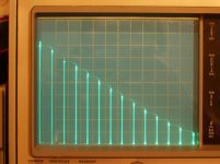
b) UnSet 6P41S Linearity 180K, 30K, 4V steps, 190V grid 2
c) UnSET 6P41S Curves 180K, 15K, 2.5V steps, 190V grid 2
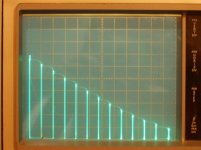
d) UnSET 6P41S Linearity 180K, 15K, 2.5V steps, 190V grid 2
a) UnSET 6P41S Curves 180K, 30K, 4V steps, 190V grid 2
b) UnSet 6P41S Linearity 180K, 30K, 4V steps, 190V grid 2
c) UnSET 6P41S Curves 180K, 15K, 2.5V steps, 190V grid 2
d) UnSET 6P41S Linearity 180K, 15K, 2.5V steps, 190V grid 2
Attachments
Last edited:
Thank you for taking the time to do this highly detailed work, a tremendous service to the diy community. I always await your posts with eager anticipation. I have read and re-read your crazy drive posts since you first tried these experiments and it seems to me that the behaviour of this Russian horizontal deflection valve is somewhat different to that of most of the cornucopia of USA sweep tubes that you have put to the test; have you any idea why this might be?
Happy to do some curves for the DIY community. I was curious about the odd 6DQ5 tubes and the 6P41S too. I like to get curves done for the tubes that don't have a full datasheet.
I'm not sure what or if the 6P41S is differerent as to Crazy drive, may just be due to it being a smaller tube than many I've traced. Also been I while since I set up for doing Crazy drive, not immediately remembering how to get it right with the R pots.
Unfortunately, I plugged in a 25HX5 tube into one of the sockets set up for 6P41S last night, to compare the tubes, and apparently I blew out some stepper V circuitry with the step current set at max. I forgot the pinout of the 25HX5 was slightly different to the 6P41S. I probably took out the current sensing resistor and maybe a regulated supply or two.
I would get to fixing it back up right away except doing taxes are looming and another project is to get one wall of the basement/floor joint waterproofed before Spring rains get here and flood my tube storage area (sitting on shelves at least). There is also a huge bush at the corner of the house that is right over the foundation drain, and nothing comes out any more. So I'm heavily over-booked for a while. But I''ll be back at it after April 15th or summer heat gets here I hope.
I have some new tubes I want to trace on the shelf already.
Oh, and I found another "ODD" 6DQ5 on EBAY last week with the plate "wings" just like the other ones tested that Davorin sent. But it requires higher Vg2 than either of the others in order to match up curves, so no matched tubes in the bunch. I'll send it back to Davorin, along with some other US type sweep tubes, since it matches a 6DQ5 well at least.
Last edited:
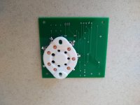
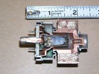
Here is my SED-Unset output test board inspired by you and George. This one is socketed for an 1625 tube, may not be the best application for Unset but I am currently fond of that tube.
I may be coming back to ask for R1 and R2 suggestions.
I may be coming back to ask for R1 and R2 suggestions.
Attachments
Dug up some sweep tubes this weekend and got busy with the uTracer.
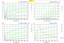
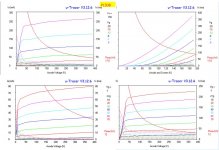
I made traces with g2 fixed 150V, triode mode, g2 drive and 'crazy drive' (g1 tied with 1k to cathode and 2k2 to g2).
First is a 6CU6/6BQ6GTB, then an EL36. Both share the same pinout, dissipation rating and heater current. Even so the 6CU6 is physically quite bigger.
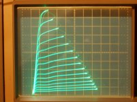
Another similarity are some funky curves at higher voltages and current. Must be oscillations. In g2 and crazy drive it's all stable.
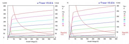
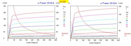
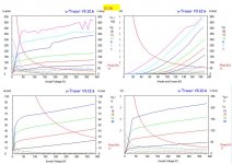
Next a PL508, a 12W vertical sweep and a bigger, unmarked tube. Both stable in g1 drive.
With these I also tried 1k and 3k9 between g2 and g1.
I'm trying to figure out how to optimize the crazy resistors.
What to aim for?
Later, I'll take a closer look at the required current for g2 vs crazy drive. The scaling makes a hard to see now, but it looks like even though the required voltage to get to a certain current is lower, the drive current is higher.
I made traces with g2 fixed 150V, triode mode, g2 drive and 'crazy drive' (g1 tied with 1k to cathode and 2k2 to g2).
First is a 6CU6/6BQ6GTB, then an EL36. Both share the same pinout, dissipation rating and heater current. Even so the 6CU6 is physically quite bigger.
Another similarity are some funky curves at higher voltages and current. Must be oscillations. In g2 and crazy drive it's all stable.
Next a PL508, a 12W vertical sweep and a bigger, unmarked tube. Both stable in g1 drive.
With these I also tried 1k and 3k9 between g2 and g1.
I'm trying to figure out how to optimize the crazy resistors.
What to aim for?
Later, I'll take a closer look at the required current for g2 vs crazy drive. The scaling makes a hard to see now, but it looks like even though the required voltage to get to a certain current is lower, the drive current is higher.
Attachments
Good to have some data on EL36!
E235L is electrically identical and has a much more comprehensive data sheet.
EL36 is actually really nice in triode.
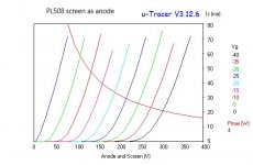
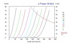
PL508 is interesting, I think you may be able to turn this tube into a triode driver if you use G2 as the anode and leave the anode unconnected.

somewhat resembles those short, but fat Compactrons
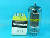
The PL508 is 30 mm diameter. For that fat look, the 17KV6A is 38 mm diameter (1.5 " ). A nice tip on top for that "original Edison" look. Good for a 24 W audio output tube. A Novar base. Very similar curves to 21HB5A.
Attachments
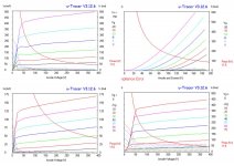
PL508 is interesting, I think you may be able to turn this tube into a triode driver if you use G2 as the anode and leave the anode unconnected.
Indeed. See the trace with the anode disconnected.
However, compare it with regular triode on the same scale...
Attachments
When the control grid and screen grid have the same pitch and same wire diameter,
If they are aligned properly, that is a type of Beam forming (multiple sheets of current).
Actually sheets of current that are similar to RF Tetrodes that have g1 and g2 aligned "Bird Cage" grids.
A 4X150 for example.
If they are aligned properly, that is a type of Beam forming (multiple sheets of current).
Actually sheets of current that are similar to RF Tetrodes that have g1 and g2 aligned "Bird Cage" grids.
A 4X150 for example.
I once built a 4-65 SE amplifier, the plate was grounded . . .
Just for safety's sake, but it would have been extremely low plate current with it and the screen tied together, when there was only about 350V B+, (B+ limited by the power transformer that was re-purposed from a 45 amplifier).
The 4-65 screen is rated at 10 Watts, and so I used the screen as if it was a "plate".
The PL508 screen is only rated for 3 Watts, or 4 Watts absolute maximum.
Last edited:
Found this for sale on eBay.
1/2 4CX250B Transmitter Tube, Real Steampunk | eBay
1/2 4CX250B Transmitter Tube, Real Steampunk | eBay
Attachments
I'd keep away from beryllium oxide as far as possible . It's carcinogenous.
Last year I've disassembled a scrapped RF transmitter (don't know exactly what it was) for it's massive heatsink. All power devices were attached to the sink via BeO insulators, so I submerged the unit under water during the disassembling procedure:
Best regards!
. It's carcinogenous.Last year I've disassembled a scrapped RF transmitter (don't know exactly what it was) for it's massive heatsink. All power devices were attached to the sink via BeO insulators, so I submerged the unit under water during the disassembling procedure:
Best regards!
Last edited:

- Home
- Amplifiers
- Tubes / Valves
- Those Magnificent Television Tubes