When researching cutting lathes 4CK250A ( ? my writing) was said to be 10 times more powerful than 6L6GC.
Yes, I believe you are talking about the 4CX250. I must first offer this WARNING. The 4CX250 is an EXTERNAL ANODE tube!!!! The plate IS the outside metal case of the tube.....touch it and you are probably DEAD!
The 6L6GC is rated for 25 watts of plate dissipation, the 4CX250 is rated for 250 watts. This makes it 10 times more powerful. There are 150 and 350 watt versions that are the same size. The 4X150 uses a glass seal, hence no "C" in the type number. The 4CX350 is a higher temp version of the 4CX250. All of the "350s" that I have seen have pink ceramic instead of the white stuff used in the 250.
Typical audio applications for a pair of 6L6GC's make 40 watts from 375 volts and 50 watts from 425 volts. A pair of 4CX250's will make 400 watts on 1600 volts and 600 watts on 2000 volts. They require a lot of forced air cooling blown through the fins on the plate at this power level. This is usually accomplished with a rather loud blower pumping air into the chassis which escapes through the chimney in the special Eimac socket. A whistling sound at the rated airflow level is not uncommon.
The tubes will physically fit a standard LOCTAL (not octal) socket and it is possible to make a chimney from PVC pipe, making the plate connection with a hose clamp.
I briefly experimented with a pair of these in a guitar amp application. It is not trivial to make an amp with these tubes that remains distortion free from less than a watt, to 500 watts, and does not oscillate at RF.
I did manage to make a RF amp that put out 250 watts on 146 MHz using a pair of these with a copper pipe resonant plate line. It ran reliably for about 2 years until I built a solid state amp that made more power from 48 volts! I sold the amp and all the spare tubes at a hamfest.
It seems a tube for running electrostatic speakers directly. 813 also? Thanks for the advice. Colleen hates me working on tubes. As I tell her even a toaster is dangerous. I doubt any tube amp is safe really? I was working on florescent strip lights live last night ( my choice and made the job quicker ). Even that was unsafe.
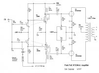
Bob Danielek designed an amp using the 3CX300A for 600 watts; I made one using the same tube based on a Japanese design, Push pull from Glass audio. I started off using the 4CX250 wired as a triode later changed it to the 3CX300A when I got some cheap. I used about 450 volts; you just need a computer fan underneath each tube. Amp has run for many years, just recently the Toroidal shorted out, so need to get it running again. I have the output tubes under cover, so you can't touch them!!! 1900 ohms Plate to plate.
Phil
Phil
Attachments
Yes, I believe you are talking about the 4CX250. I must first offer this WARNING. The 4CX250 is an EXTERNAL ANODE tube!!!! The plate IS the outside metal case of the tube.....touch it and you are probably DEAD!
The 6L6GC is rated for 25 watts of plate dissipation, the 4CX250 is rated for 250 watts. This makes it 10 times more powerful. There are 150 and 350 watt versions that are the same size. The 4X150 uses a glass seal, hence no "C" in the type number. The 4CX350 is a higher temp version of the 4CX250. All of the "350s" that I have seen have pink ceramic instead of the white stuff used in the 250.
Typical audio applications for a pair of 6L6GC's make 40 watts from 375 volts and 50 watts from 425 volts. A pair of 4CX250's will make 400 watts on 1600 volts and 600 watts on 2000 volts. They require a lot of forced air cooling blown through the fins on the plate at this power level. This is usually accomplished with a rather loud blower pumping air into the chassis which escapes through the chimney in the special Eimac socket. A whistling sound at the rated airflow level is not uncommon.
The tubes will physically fit a standard LOCTAL (not octal) socket and it is possible to make a chimney from PVC pipe, making the plate connection with a hose clamp.
I briefly experimented with a pair of these in a guitar amp application. It is not trivial to make an amp with these tubes that remains distortion free from less than a watt, to 500 watts, and does not oscillate at RF.
I did manage to make a RF amp that put out 250 watts on 146 MHz using a pair of these with a copper pipe resonant plate line. It ran reliably for about 2 years until I built a solid state amp that made more power from 48 volts! I sold the amp and all the spare tubes at a hamfest.
A pair of 250's should have been able to make more than twice that power, even at 2m. Were you deliberately running them conservatively?
Nowandays you can get 1200w in the 2m band with a single Freescale MRFE6VP61K25H. It takes 50V and 50A to make it happen, and you cannot skimp on the thermal management of the device.
Yes I could have squeezed more power from the 250's, but not from the power supply I had. It was rated for 1100 volts at 200 mA and I was pulling about 300 if I remember right. This was about 15 years ago, maybe more.
As a transmitter designer for Motorola for the past 41 years, I could have probably talked the Freescale rep out of one of those bad boys if I had thought about it before we were both laid off. I spent my last 4 or 5 years working on LTE at 760 MHz and 2.35 GHz, using Freescale LDMOS parts.
I picked up some scrap MRI amplifiers cheap at the Dayton hamfest over the past few years. They use box loads of MRF150's to make 1 to 5 KW pulses at 13, 27 or 40 MHz. One of them had a 48 volt 600 watt SMPS which limits the fun to about 450 watts. I built an amp that puts out about 250 W with 2 X MRF150's. I had planned to make 3 more of them and a combiner, but my job came to an end and we have recently moved. No lab, no bench, and no radios for now.
you can get 1200w in the 2m band with a single Freescale MRFE6VP61K25H.
As a transmitter designer for Motorola for the past 41 years, I could have probably talked the Freescale rep out of one of those bad boys if I had thought about it before we were both laid off. I spent my last 4 or 5 years working on LTE at 760 MHz and 2.35 GHz, using Freescale LDMOS parts.
I picked up some scrap MRI amplifiers cheap at the Dayton hamfest over the past few years. They use box loads of MRF150's to make 1 to 5 KW pulses at 13, 27 or 40 MHz. One of them had a 48 volt 600 watt SMPS which limits the fun to about 450 watts. I built an amp that puts out about 250 W with 2 X MRF150's. I had planned to make 3 more of them and a combiner, but my job came to an end and we have recently moved. No lab, no bench, and no radios for now.
Yes I could have squeezed more power from the 250's, but not from the power supply I had. It was rated for 1100 volts at 200 mA and I was pulling about 300 if I remember right. This was about 15 years ago, maybe more.
As a transmitter designer for Motorola for the past 41 years, I could have probably talked the Freescale rep out of one of those bad boys if I had thought about it before we were both laid off. I spent my last 4 or 5 years working on LTE at 760 MHz and 2.35 GHz, using Freescale LDMOS parts.
I picked up some scrap MRI amplifiers cheap at the Dayton hamfest over the past few years. They use box loads of MRF150's to make 1 to 5 KW pulses at 13, 27 or 40 MHz. One of them had a 48 volt 600 watt SMPS which limits the fun to about 450 watts. I built an amp that puts out about 250 W with 2 X MRF150's. I had planned to make 3 more of them and a combiner, but my job came to an end and we have recently moved. No lab, no bench, and no radios for now.
I've been thinking about making a legal limit HF amp using two of the Freescale devices. In theory, a single device will do 1300 watts, but the reality is that they generate quite a bit of IMD at that power level due to their decreasing linearity above 800W. The IMD is tolerable at VHF, but it's too much for the HF bands. So, I figure a pair running at 750W each into a single broadband output transformer would be a good solution. Cost for the devices is about the same as a single used 8877. Where the project saves money is the availability of inexpensive used 48V 50A Telco switching supplies. Between that and the lack of expensive vacuum capacitors the cost should come in about the same as an equivalent power tube amp. Maybe even a bit less.
I haven't worked with any new LDMOS devices larger than the MRF9060 (or whatever it's new number is). Those and all the smaller Freescale devices tend to produce lower IMD by running the B+ near the upper limit. LTE has strict emission mask requirements that need extremely low IMD. I ran the 28 volt devices at 32 volts which made 160 watts of CW at 760 MHz. The RF drive was then limited to cap the power at 120 watts peak to survive VSWR testing. LTE has a 10 db peak to average ratio, so you need a 120 watt amplifier for a 12 watt PA to avoid clipping the peaks and creating distortion. The losses through the harmonic filter and duplexer were almost 3 db so this huge 20 pound brick was rated at 5 watts of LTE power!
Using 2 devices in push pull will reduce the even harmonics making the harmonic filter a bit easier.....If you are going to cover all of HF, how are you going to switch the filter? Relays. PIN diodes, even the big ones from MaCom explode at this power level.
Using 2 devices in push pull will reduce the even harmonics making the harmonic filter a bit easier.....If you are going to cover all of HF, how are you going to switch the filter? Relays. PIN diodes, even the big ones from MaCom explode at this power level.
Wow tubelab sorry about the layoff. I am well into my 7th decade of life and still working in Silicon Valley. You might want to connect with me on LinkedIn if you are still interested in doing the corporate thing; the headhunters out here love to see my grizzly visage when they need hardcore analog designs that work. My project at the corp is a Class E HF plasma generator running plate modulation via an SMPS controlling the rail. Yup the output device is a Freescale power MOS.
I haven't worked with any new LDMOS devices larger than the MRF9060 (or whatever it's new number is). Those and all the smaller Freescale devices tend to produce lower IMD by running the B+ near the upper limit. LTE has strict emission mask requirements that need extremely low IMD. I ran the 28 volt devices at 32 volts which made 160 watts of CW at 760 MHz. The RF drive was then limited to cap the power at 120 watts peak to survive VSWR testing. LTE has a 10 db peak to average ratio, so you need a 120 watt amplifier for a 12 watt PA to avoid clipping the peaks and creating distortion. The losses through the harmonic filter and duplexer were almost 3 db so this huge 20 pound brick was rated at 5 watts of LTE power!
Using 2 devices in push pull will reduce the even harmonics making the harmonic filter a bit easier.....If you are going to cover all of HF, how are you going to switch the filter? Relays. PIN diodes, even the big ones from MaCom explode at this power level.
Actually, each MRFE device is a PP pair in a single package. The entire amplifier would be essentially just a standard 4-MRF150 600 watt amp scaled up 250%. Relays would be used for filter switching. I was planning on using high power stud mount PIN diodes for T/R switching, with vacuum relays being the backup plan.
12EN6 looks to be very similar to 12L6 or 12W6 tubes.
http://www.diyaudio.com/forums/tube...nificent-television-tubes-17.html#post3861718
http://frank.pocnet.net/sheets/127/1/12EN6.pdf
http://frank.pocnet.net/sheets/127/1/12W6GT.pdf
http://frank.pocnet.net/sheets/127/1/12L6GT.pdf
http://frank.pocnet.net/sheets/093/2/25L6GT.pdf
http://frank.pocnet.net/sheets/093/6/6W6GT.pdf
yes, despite their lower plate rating than the 12W6, i plugged them in anyway....i was truly rewarded....
")


All of this TV tube talk is fascinating, but schematics would help those of us that don't have much experience with non-standard guitar amp tubes.
I have several hundred TV/Radio tubes and would love to build some hi-fi monoblocks with them if possible.
as you probably know by now, TV power tubes like lower g2 voltages than the regular audio power tubes, so that voltage doubler type psu's are very effective here...
and do not be dismayed by the lower plate ratings, they can survive higher plate watts...
finally the cathode ratings are far bigger than most of the audio power tubes, yes more than the kt150...
An example:- Guitar Amp with Sweep Tube Outputs and ECF80/6BL8 phase splitter.
Note the method of deriving a 1/2B+ supply from the power tranny Centre Tap to fed the screens.
http://www.ozvalveamps.org/playmaster/pm117cct60w2.gif.
Cheers,
Ian
Note the method of deriving a 1/2B+ supply from the power tranny Centre Tap to fed the screens.
http://www.ozvalveamps.org/playmaster/pm117cct60w2.gif.
Cheers,
Ian
Well, it's a vertical sweep for color TV instead of a horizontal sweep. 19 Watts, like a bigger 6LU8 pentode.
An update on my common sweep tube list with a bit more info:
List of knee currents for g2 = 150 V, g1 = 0 V, Vp = 60 to 80 V
<tube> <Watts> <mA knee@150Vg2> <gm> <Mu> <maxDCmA> <registered by> <date>
6LF6 40W 1144mA@150V 15K@125mA Mu3 500mADC Amperex 1968
6KG6/EL509 34W 1135mA@150V 13K@150mA Mu3.2 500mADC Amperex 1965
6MC6 33W 1130mA@150V 14K@125mA Mu4 400mADC RCA (6LX6 clone) 1972
13E1 90W(absmax) 1120mA@150V 35K@500mA Mu4.5 800mADC AEI 1961
6MH6 38.3W 1100mA@150V 14K@125mA Mu4 500mADC GE (up-rated 6LX6,6KD6,26HU5) 1972
6MB6 38W 1085mA@150V 14K@110mA Mu3.5 400mADC Sylvania 1971
6LR6 30W 1085mA@150V 16K@140mA Mu3.5 375mADC Sylvania 1968
6LX6/6KD6/26HU5 33W 1080mA@150V 14K@125mA Mu4 400mADC GE 1969/1965/1969
6LW6 40W 1050mA@150V 12K@125mA Mu3.7 400mADC GE 1971
6KN6 30W 1050mA@150V 16K@100mA Mu4.5 400mADC Sylvania 1965 (later versions are 6KD6)
6LZ6 30W 940mA@150V 11K@140mA Mu3 350mADC RCA 1971
6LB6/A 30W/35W 825mA@150V 13.4K@105mA Mu4 315mADC GE 1967
6JE6C/6JS6C 30W 789mA@150V 10.5K@130mA Mu3 350mADC Sylvania 68/69
6JE6 24W 762mA@150V 9.6K@115mA Mu3 315mADC RCA 1962
6JS6/6HF5 28W 749mA@150V 11.5K@130mA Mu3 315mADC GE 1964/1963
6MJ6 30W 740mA@150V 11K@100mA Mu3.6 350mADC RCA 1973
6LG6 28W 740mA@150V 11.5K@90mA Mu3.6 315mADC GE 1967
6LQ6 30W 715mA@150V 7.5K@95mA Mu3 350mADC RCA 1967
6ME6 30W 700mA@150V 9.6@130mA Mu3.5 350mADC RCA 1971
6DQ5 24W 690mA@150V 10.5K@110mA Mu3.3 315mADC RCA 1957
6JF6/6JG6 17W 660mA@150V 10K@80mA Mu4.1 275mADC RCA 1965/1964
6KM6 20W 630mA@150V 9.5K@80mA Mu4 275mADC RCA 1965
6HD5/6HJ5 24W 630mA@150V 10K@80mA Mu4.2 280mADC Raytheon 1962/1963
6JR6/6JU6 17W 600mA@150V 7K@45mA Mu4.7 275mADC RCA 1968/1966
6JZ6/21HB5A 18W 560mA@150V 9K@46mA Mu4.8 230mADC GE 1966/1964
12HE7 10-15W 540mA@150V 8.8K@60mA Mu4.2 200mADC GE (15W if damper disabled) 1964
6CL5 25W 514mA@150V 6.5K@90mA Mu3 240mADC Sylvania 1955
6GB5/29KQ6/EL500 17W 500mA@150V 13K@100mA Mu5.1 275mADC Amperex 1961/Matsushita 1959/Philips 1961?
6KV6/A 20-28W 488/610mA@150V 6K@40mA Mu4 275mADC RCA (re-rated 6KM6?) 1967/1969
6HB5/6GY5/21JV6/6KE6/16KA6 18W 475mA@150V 9.1K@50mA Mu4.7 230mADC GE/GE/GE/Ray/Tung 1962/1962/1965/1965/1964
6EX6 22W 460mA@150V 7.7K@67mA Mu4.2 220mADC Raytheon (up-rated 6CD6) 1959
6CB5/A 23W 440mA@150V 8.8K@90mA Mu3.8 240mADC RCA 1954/1956
6CD6/GA 15/20W 422mA@150V 7.7K@75mA Mu3.9 200mADC RCA/GE 1949/1954
6GT5/6GJ5/6JT6/6JB6/6GW6 17.5W 380mA@150V 7.1K@70mA Mu4.4 175mADC RCA 1961/1961/1964/1962/1961
6GE5 17.5W 350mA@150V 7.3K@65mA Mu4.4 175mADC GE 1961
6GF5 9W 345mA@150V 4.7K@34mA Mu4.2 160mADC GE 1961
6JM6/6JN6/6FW5/6GC6 17.5W 340mA@150V 7.3K@70mA Mu4.4 175mADC GE 1964/1964/1960/1960
6DQ6B/6GV5 17.5W/18W 330mA@150V 7.3K@65mA Mu4.4 175mADC GE 1959/1962
6DQ6/A 18W 280mA@150V 6.6K@55mA Mu4.1 120/155mADC CBS/RCA 1955/1956
6JA5/10JA5 19W 276mA@150V 10.3K@95mA Mu5.5 110mADC GE 1971
6LU8/6LR8/6MY8 14/16W 265mA@150V 9.3K@56mA Mu7 75mADC Sylvania 1964/1964/1970(Tungsol)
6AV5/GA///6BQ6/GA 11W 255ma@150V 5.9K@57mA Mu4.3 110mADC CBS/GE 1949/1955 /// CBS/Syl 1949/1953
KT120 60W 221ma@150V
KT90 50W 220mA@150V
6Y6G/GT/GA 12.5W 200mA@150V Ray 1937/KenRad 1939/Syl 1954
6550A 35W 190mA@150V
6W6GT 10W 185mA@150V CBS 1939
KT88 35W 170mA@150V
6CA7/EL34 25W 107mA@150V Philips 1952
6JC5 19W 80mA@150V Sylvania 1971
6L6/G/GA/GB/GC 30W 77mA@150V RCA 1936/Ray 1936/Syl 1943/Syl 1954/GE 1958
6HB6 10W 70mA@150V Raytheon 1961
6GK6 13.2W 65mA@150V CBS 1959
6BQ5/EL84 12W 65mA@150V Rogers 1956
6V6G/GT 14W 45mA@150V KenRad 1936/CBS 1939
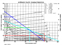
is 10JA5 considered a sweep tube?
Yep: the 10JA5 is a vertical deflection power amp for wide screen color TV CRTs. It also looks to be quite promising as an audio final, even if there's no mention of audio. Pretty good loadline (attached). Unlike the horizontal deflection types, it can use a more common 5K44 (P-2-P) OPT, and that should come close to a stock value, so no need to have a special OPT wound for it.
The loadline has a mistake: the h3= 0.02%, not 3.0%. even at the higher estimate, it looks pretty good over the full output. As for how that works out in practice, listening tests will tell. I have a few of these myself. If they work anything like the HD types, the output should be quite clean.
All of this TV tube talk is fascinating, but schematics would help those of us that don't have much experience with non-standard guitar amp tubes.
I have several hundred TV/Radio tubes and would love to build some hi-fi monoblocks with them if possible.
I put up a schemo for the Le Renard on the first page that uses a whole bunch of TV t00bz: 6BQ7 pre/phase splitter and 6BQ6GA finals. More TV types in the screen supply.
Attachments
Last edited:
- Home
- Amplifiers
- Tubes / Valves
- Those Magnificent Television Tubes