OK,
The Vifa aluminum mid bass, the Constant Directivity (Mick Jagger lips) horn and a couple of handfuls of resistors are on their way from PE. Should pass through Customs in a couple of weeks. Have to wait till they're here before I can even make the brackets for the tweeters. Cabinets sanded, cleaned and painted (spraybomb)
Will post results.
If worthy")
Cal
The Vifa aluminum mid bass, the Constant Directivity (Mick Jagger lips) horn and a couple of handfuls of resistors are on their way from PE. Should pass through Customs in a couple of weeks. Have to wait till they're here before I can even make the brackets for the tweeters. Cabinets sanded, cleaned and painted (spraybomb)
Will post results.
If worthy
Cal
Cal Weldon said:Here are the ports glued to the tweeter face plates.
Whoops
Attachments
Well I recommend 750uF to 1000uF in series (bypassed
nonpolar electrolytics) if you want to ply them with some
serious juice.
Filling the ports with drinking straws may help somewhat.
Asumming you are using the original first order parallel c/o
I'd also recommend repacing the capacitor with a better
type, adding the RLC network with R 2 to 3 ohms to the
bass unit , and adding an inductor in parallel with the
tweeter for cleaner treble.
sreten.
Well it is indeed a 2nd order i loaded up LSP to check the target I mean.
I suppose yes the C and the R in parallel will work as a zobel to a certain extent. But I have found that adding a small amount of resistance in series with the shunt cap in a lowpass adds a bit more "pull" to the filter removing small peaks in the xover region.
Eitherway why wont the parallel filter work? it works great in the simulation, removing the notch worsens the response. Yes you are right in saying the notch i a little narrow I have now altered the xover a little.
Gimme your opinion of the new filter, I have also sorted out the component values and got them to match standard values available.
Right the filter is 2nd order electrical! but with a resistor added to provide response shaping. This does not act a a zobel and the impedance shows this. Then there is the notch filter.
I can try for the notch filter in series with the driver if you think it is necessary, do 2nd order electrical and parallel not work?
Attachments
Hi Matt,
A 6R to 8R damping resistor moves it very near to a
Zobel, even if the the capacitor is not a zobel value.
Generally (without the damping resistor) a shunt
RLC network does not work well in parallel with
the shunt capacitor, but as you've added a series
resistor to the capacitor things are different.
But I will point out due to the series resistor final
roll-off is 6dB/octave, its a first order with response
shaping not second order.
A parallel shunt RLC works well with odd order parallel
crossovers, which due to your series R with the capacitor
is what this is.
Series notch filters are needed for even order parallel
networks, parallel notch filters do not work well.
Still in terms of keeping it simple parallel first order on
the bass unit (with shunt RLC) and second order on
the treble sounds sensible to me.
If things look better to you with the added parallel RC
then fine, your helping and I certainly don't want you
to think I don't appreciate this.
sreten.
A 6R to 8R damping resistor moves it very near to a
Zobel, even if the the capacitor is not a zobel value.
Generally (without the damping resistor) a shunt
RLC network does not work well in parallel with
the shunt capacitor, but as you've added a series
resistor to the capacitor things are different.
But I will point out due to the series resistor final
roll-off is 6dB/octave, its a first order with response
shaping not second order.
A parallel shunt RLC works well with odd order parallel
crossovers, which due to your series R with the capacitor
is what this is.
Series notch filters are needed for even order parallel
networks, parallel notch filters do not work well.
Still in terms of keeping it simple parallel first order on
the bass unit (with shunt RLC) and second order on
the treble sounds sensible to me.
If things look better to you with the added parallel RC
then fine, your helping and I certainly don't want you
to think I don't appreciate this.
sreten.Oh im certainly not thinking that you dont appreciate my help im also learning too and just asking questions about things to further my understanding.
This seems to fit in with my latest speaker which used a RCL on a tweeter with a 2nd order highpass, the RCL was used to tame a peak in the trebble response but opon measuring the finished speaker the peak was still there, even though it was not as bad as if the notch was removed. I had thought it could have been to do with component tollerance, a small change in the capacitor value does indeed alter the notch frequency quite cosiderably. So I had thought it was that, sounds like it being 2nd order could have also influenced the final result too.
This seems to fit in with my latest speaker which used a RCL on a tweeter with a 2nd order highpass, the RCL was used to tame a peak in the trebble response but opon measuring the finished speaker the peak was still there, even though it was not as bad as if the notch was removed. I had thought it could have been to do with component tollerance, a small change in the capacitor value does indeed alter the notch frequency quite cosiderably. So I had thought it was that, sounds like it being 2nd order could have also influenced the final result too.
Just out of interest how do you use a parallel notch filter? Im assuming you mean the electrical configuration is the RLC in parallel with each other and then placed in series with the driver, before the filter?
I've tried numerous attempts at getting one of these to work altering values by hand, letting the LSPcad wizard have a go and letting the system optomiser run, but nothing seems to be able to work im removing the res peak. Is there some kind of special way of using these?
I've tried numerous attempts at getting one of these to work altering values by hand, letting the LSPcad wizard have a go and letting the system optomiser run, but nothing seems to be able to work im removing the res peak. Is there some kind of special way of using these?
A series notch filter (all components in parallel) needs a fairly
high resistance to work well. They are not cost effective as
the the components carry the full signal, and generally are
avoided if a parallel RLC can be substituted.
Generally for resonance suppression above crossover a parallel
RLC suits odd order parallel c/o's and even order series c/o's.
sreten.
high resistance to work well. They are not cost effective as
the the components carry the full signal, and generally are
avoided if a parallel RLC can be substituted.
Generally for resonance suppression above crossover a parallel
RLC suits odd order parallel c/o's and even order series c/o's.
sreten.sreten said:Well I recommend 750uF to 1000uF in series (bypassed
nonpolar electrolytics) if you want to ply them with some
serious juice.
(This sounds like a good idea)
Filling the ports with drinking straws may help somewhat.
(Can't... I'm using the drinking straws right now.)
Asumming you are using the original first order parallel c/o (yes I am)
I'd also recommend repacing the capacitor with a better (poly, yes?)
type, adding the RLC network with R 2 to 3 ohms to the
bass unit , and adding an inductor in parallel with the
tweeter for cleaner treble.
Thanks sreten,
I think for now I will leave it as a series 3mfd to the tweeter and only add a coil if the overlap is too much for the ears. Remember, the low pass is .55 mH so there is already a wee bit of a drop there. Besides, these are for show more than anything else. I will be running them on a friendly little 130 wpc Fisher integrated. The CA-915 if I remember correctly.
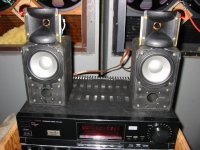
I have the big outdoor system, the medium outdoor system, the small outdoor system, the house system, the downstairs system and so on. I just had a couple of beers one night and I was thinking about brothers for some reason. So I just wondered if the A7's would like some little brothers. That's all there is to this.
I have that Parts Express EQ unit (Audio Source?) and it will help with this little bit of fun I having. Hey it's great to deal with something so small that it's like playing with a baby.
Thanks Matt for all the graphs and suggestions, it may be that I decide to take this further but I'm not sure it's worth doing anything so fancy...yet. It might make sense if we could increase the size of the box but...
Cal
The coil on the tweeter is not suggested for frequency response.
Its a lot more to do with distortion and unecessary excursion,
its main purpose is reducing excursion below the c/o frequency
of the tweeter.
note that below c/o for first order excursion still increases
6dB per octave down to the Fs of the tweeter.
a good choice of parallel resistor for the L-pad will
control any Fs impedance peak if the tweeter has one.
sreten.
Its a lot more to do with distortion and unecessary excursion,
its main purpose is reducing excursion below the c/o frequency
of the tweeter.
note that below c/o for first order excursion still increases
6dB per octave down to the Fs of the tweeter.
a good choice of parallel resistor for the L-pad will
control any Fs impedance peak if the tweeter has one.
sreten.sreten said:The coil on the tweeter is not suggested for frequency response.
Its a lot more to do with distortion and unecessary excursion,
its main purpose is reducing excursion below the c/o frequency
of the tweeter.
note that below c/o for first order excursion still increases
6dB per octave down to the Fs of the tweeter.
a good choice of parallel resistor for the L-pad will
control any Fs impedance peak if the tweeter has one.
Hi sreten, thanks for your input.
1. My only concern using the coil is that the existing XO has a drop out already in the mids. Going from 6 to 12dB will cause even more drop out.
2. If there is harshness, I will fool around with it.
3. Excess excursion and or power handling might not be a problem, I will be attenuating this with resistors both series and parallel.
4. I can't remember the last system I put together than ran only a cap on the tweeter. It is likely I will want to play with this.
5. If all else fails, I have an EQ to smooth the rough waters.
Happy sailing,
Cal
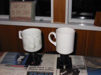
Parts arrived this morning, so this afternoon I kicked off a little early and started to assemble. Well, the holes didn't line up with the woofer, so I had to modify the baskets. Then she wouldn't fit properly so I had to notch the lip at the top of the cabinet. Then I went down to Home Depot, got some brackets for the tweeters and well, the holes didn't line up so I re-drilled those and bolted them on. Drilled a hole for the wires and well, I couldn't fit the wires through without squashing the connectors. I didn't want a great big hole in the top of the cabinets, so I flattened and then straightened them back out.
I have the original XO being used with no resistors on the tweeter.
Now about those ports:
Open, they sound like absolute (insert bad word here)
Stick a cork in them and these little things made me smile. It doesn't really look like a small A7 like I might have hoped, but so what. They sound just great!
Here's a pic at this stage,
Cal
Attachments
Ok, a little correction. I had hooked them up to the test leads and I forgot I was running it through the 1.5mH cap soldered to the driver. I started to actually listen to a couple of songs and where is the midrange? Oops.
So now they are running through the original XO with a 5.6 ohm in series and a 7.5 ohm in parallel after that. Moocho Goodo.
I just listened to Bruce Cockburn at about 10 watts and I was impressed.
Just need some corks to fill the port holes. Duct tape just doesn't cut it/
Cal
Happy father of two wonderful little squawkers
Latest idea:
If I make a pedestal stand for these to act also as an enclosure, could I use 2" ID steel pie for the upright and a weighted wood base? I would would open up the bottom of the original cabinets and end up with a total volume of about an eighth of a cu ft.
I like the look of it in my head but I'm wondering about the 2" connecting pipe upright. Is that too small a tube?
This idea would give me room to put in a new crossover.
Any thoughts?
Cal
- Status
- This old topic is closed. If you want to reopen this topic, contact a moderator using the "Report Post" button.
- Home
- Loudspeakers
- Multi-Way
- Those aluminum mini speakers