Re: Re: Sings sweetly...
I wasn't complaining about that, just pointing out that one might find some different values. I'm using a E88CC, but will try a "plain" 6DJ8 to see if it makes any difference.
But as said before it is sound that matters, and I like it.
Thanks Thorsten.
Hi Carsten,
unfortunately I don't have AD844 handy.
As you can see my board is from the very first version that didn't include I/V on board.
As the trafo has a dual 18V secondary unused I will probably build Jocko's simple I/V to see which I like best.
The other circuit proposed by T. with OPA660 sounds excellent but uses much lower rails and for the moment I don't feel like adding another transformer.
Cheers
Andrea
Kuei Yang Wang said:Konnichiwa,
My numbers are for a "bogey" 6DJ8, the 6922 and 7308 et al will differ enough to throw the numbers out a little. The Choke loaded version would simply let the circuit find it's own right current.
Sayonara
I wasn't complaining about that, just pointing out that one might find some different values. I'm using a E88CC, but will try a "plain" 6DJ8 to see if it makes any difference.
But as said before it is sound that matters, and I like it.
Thanks Thorsten.
carawu said:Hmmmm Andrea,
what about the sound?
Please tell us your "earing" about Pedja´s I/V with AD844 versus T´s Ecc88 circuit?
Carsten
Hi Carsten,
unfortunately I don't have AD844 handy.
As you can see my board is from the very first version that didn't include I/V on board.
As the trafo has a dual 18V secondary unused I will probably build Jocko's simple I/V to see which I like best.
The other circuit proposed by T. with OPA660 sounds excellent but uses much lower rails and for the moment I don't feel like adding another transformer.
Cheers
Andrea
Audible hum on Kuei output stage
I have built the "ultimate" tube output stage suggested by Kuei Yang Wang. It has the following characteristics:
Tube: NOS Mullard E88CC
Anode load: 140H choke with 1400 ohm DCR
Anode current: 12 mA
Anode-Cathode voltage: 50V
Grid-Cathode voltage: -0.22 V
Anode supply: full wave tube rectifier EZ90, 220uF+20H+220uF filter.
Heather supply: 6.1 AC V RMS for both E88CC and EZ90 (they share the same transformer secondary).
At first listening test, the dac sounds good, but it has an AUDIBLE HUM.
I have tried several grounding schemes but did not succeed in eliminating that hum.
Have you any ideas to solve this problem?
Best regards.
Paul
Re: Audible hum on Kuei output stage
I am not one of the experts but....
Run your HV supply through Duncan's PS tool. Is the heater supply connected to ground at the centertab (with R) or... did you try feed the E88CC's with DC? EZ90 and E88CC on same sec, hmmmmm.
What filter did you use after 1541 and which 150H chockes? I have a CD60 with lots of space, so curious...
Thanks,
Jeroen
Sandor said:I have built the "ultimate" tube output stage suggested by Kuei Yang Wang. It has the following characteristics:
Tube: NOS Mullard E88CC
Anode load: 140H choke with 1400 ohm DCR
Anode current: 12 mA
Anode-Cathode voltage: 50V
Grid-Cathode voltage: -0.22 V
Anode supply: full wave tube rectifier EZ90, 220uF+20H+220uF filter.
Heather supply: 6.1 AC V RMS for both E88CC and EZ90 (they share the same transformer secondary).
At first listening test, the dac sounds good, but it has an AUDIBLE HUM.
I have tried several grounding schemes but did not succeed in eliminating that hum.
Have you any ideas to solve this problem?
Best regards.
Paul
I am not one of the experts but....
Run your HV supply through Duncan's PS tool. Is the heater supply connected to ground at the centertab (with R) or... did you try feed the E88CC's with DC? EZ90 and E88CC on same sec, hmmmmm.
What filter did you use after 1541 and which 150H chockes? I have a CD60 with lots of space, so curious...
Thanks,
Jeroen
Thanks Jeroen,
I am going to try DC supply for the heathers.
The filter is the anti-sinc proposed by Kuei Yang Wang in this same thread.
The choke (140H, 1400 ohm DCR) is model Z37 from "Elettronica Novarria" (www.elettronicanovarria.com) , here in Italy. It looks good and is cheap, but not so small...
Regards.
Paul
Ciao Paolo,
I'd separate filament supplies and regulated DC for the E88CC.
I also use some Mullards, and my setup is dead quiet.
Try using Duncan's PSU designer, the 220uF cap just after a tube rectifier seems a attempt to shorten its life ;-)
Let us know how it works
Cheers
Andrea
I'd separate filament supplies and regulated DC for the E88CC.
I also use some Mullards, and my setup is dead quiet.
Try using Duncan's PSU designer, the 220uF cap just after a tube rectifier seems a attempt to shorten its life ;-)
Let us know how it works
Cheers
Andrea
Hello Andrea,
I'll follow your suggestions, starting with DC heather supply because there is no spare space for an other transformer.
Do you have shields between supply, analog stage and digital stage? Do you think shields would carry any benefit?
The supply circuit has a 390 ohm resistor in series after the rectifier. "PSU Designer" simulation looks good. Do you think that 220uF is still too much for the first capacitor?
Ciao.
Paul
Ciao Paolo,
where did you connect the filaments?
They should not be left floating.
Usuallly rectifiers have heater tied to the cathode (but this is critical only with higher voltages), but in this case I think you should reference heaters to gnd (if they use the same supply - but I'd separate them).
If the series resistor prevents the tube from exceeding its maximum peak current (PSU designer gives a warning if it happens) you are OK.
I don't use shields whatsoever ;-) but a copper board with a hole for the socket and some slots to separate copper areas for the supplies (I use solid-state soft rectifiers and multiple C-R-C stages for each tube). Maybe adding a R-C cell per anode will help in your setup.
Cheers
Andrea
Thanks.
I have tied heathers to ground, but no effect on hum.
I am going to modify the anode supply this way:
1) No series resistor after the rectifier.
2) Lower value for the first capacitor (22 or 47 uF)
3) An RC net after the second capacitor, one for each anode (Andrea's suggestion).
Separate supply for the two heathers is a better solution but in the box there is no space for one more transformer. My plan is to feed the EZ90 heather with AC, and connect the same sec. to a bridge rectifier and a capacitor to feed E88CC heather. Is that a worthy solution?
Regards.
Paul
Thanks Carsten,
the circuit is the output stage proposed by Kuei Yang Wang in this same thread. Its input has a low-pass filter for frequencies above 20KHz, so HF signals are not supposed to enter the grid. Input impedance is very low, about 50 ohm. Moreover the grid never goes positive. Is a grid stopper still necessary?
Regards.
Paul
Attachments
JC951t said:Hi,
Can this circuit be directly applied
on a parallel TDA1541 dac ?
Thanks
With some modifications to avoid the DACs exceeding their voltage compliance you can use this circuit.
You need to halve the impedance of the network connected at the DAC (= halve resistors and indictances and double the caps).
Cheers
Andrea
Re: Re: Audible hum on Kuei output stage
I have used a separate DC supply for the E88CC heater. Hum is still there.
The grid stoppers have not solved the problem.
What else can I try?
Best regards.
Paul
JeroenR said:
did you try feed the E88CC's with DC? EZ90 and E88CC on same sec, hmmmmm.
I have used a separate DC supply for the E88CC heater. Hum is still there.
carawu said:
please try a gridstopper...
100R till 1k...
The grid stoppers have not solved the problem.
What else can I try?
Best regards.
Paul
Re: Re: Re: Audible hum on Kuei output stage
Carsten
Please post a picture.Sandor said:
The grid stoppers have not solved the problem.
What else can I try?
Carsten
Hello,
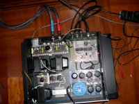
here is a picture of the DAC I have built.
The analog section is on the left. From top to bottom:
- The KYW output stage with the E88CC. That yellow/blue wire connects to an external heater DC supply.
- The two anode load chokes (140H, 1400 ohm DCR)
- The anode PSU with the EZ90
- The transformer (90+90V and a single 6.3V) and the PSU choke (20H)
The digital section is on the right. From top to bottom:
- The digital board (CS8412 + TDA1541A)
- The PSU (regulated +-18V).
That floating wires are for experimental grounding.
It sounds good but has an audible hum and nothing seems to work to
solve this problem.
Help!!!
Thanks.
Paul
Attachments
Hi Sándor,
I recommend the following:
1.) Disconnect the DAC from the tubes. If the hum is still there, it is in the tube stage. If not, there is a ground loop with the DAC.
2.) One end of the filament should be grounded.
3.) Inter-stage shielded wire is not always a good idea. Try twisted wire from UTP Ethernet cable.
4.) I would not put the AC socket so dangerously close to the analog stage.
5.) A good test is to disconnect the AC power from the three transformers one-by-one with a temporary switch (with caution, shock hazard!) for a few seconds, and see if the hum ceases.
Hi,
do you have access to a scope?
If so give a look at the hum waveform and see if it is related to the PSU ripple.
The P2P assembly is way too big imho, and since we are dealing with mV levels at the tube's grids the AC inlet seems too close.
Try moving the I/V pcb outside the case.
It also seems that you used 2 shielded wires from DAC to I/V, how are the gnds connected?
If you only connect a single channel output does the hum stop?
Cheers
Andrea
PS You live in Milan or in the surroundings?
- Status
- This old topic is closed. If you want to reopen this topic, contact a moderator using the "Report Post" button.
- Home
- Source & Line
- Digital Source
- Thorsten's Valve Output Stage with TDA1541DAC