Opened a webpage about this project.
DC coupled Hi-end Hybrid Amplifier
In the listening test with some my friends were overcome a lot of the performance of my previous End Amplifier
Amplifier End by Andrea Ciuffoli
DC coupled Hi-end Hybrid Amplifier
In the listening test with some my friends were overcome a lot of the performance of my previous End Amplifier
Amplifier End by Andrea Ciuffoli

Trivial problem, feedback has to go from the other side of the circlotron. However, the phase then relies on the input transformer to do correct phase splitting. Otherwise, your input stage (1st) must be set up as a differential amplifier so it does the phase splitting itself. Feedback can still be connected to the 1st stage cathodes, but I'll leave it to you to figure it out, it's not too difficult ")
Looks like all the circuit ramblings have missed the obvious TEM3200 front end design.
The EC86 and CV6189 are both hi gm tubes. So use them together as an asymmetric differential pair (a separate pair on each phase side). Input goes to the EC86 grid, and N Fdbk goes to the CV6189 grid. CCS tails for each side (notice -Ub for each side). Plate of the CV6189 drives the 6S3P cathode follower grid.
Edit:
Looks like the 6S3P is the input, and the CV6189 is the 2nd half of the diffl pair, with the EC86 as the follower here: http://www.6moons.com/audioreviews/thorens/thorens.html
Essentially a tube Op-Amp version of the SUMO9+
Attachments

Last edited:
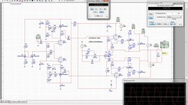
Hello, I simulated the patent with OPAMP :
0.001% 10khz 1W 8ohm (4V)
0.02% 10khz 120W 4ohm (31V)
https://sites.google.com/site/solidcirclotron/OPAtriple.asc

I tried with a follower but it does not work
https://sites.google.com/site/solidcirclotron/CircloOpaBuffer.asc

0.001% 10khz 1W 8ohm (4V)
0.02% 10khz 120W 4ohm (31V)
https://sites.google.com/site/solidcirclotron/OPAtriple.asc
I tried with a follower but it does not work
https://sites.google.com/site/solidcirclotron/CircloOpaBuffer.asc
What is the problem with the buffered version? Oscillating? Maybe need fast Fet buffers.
------------------
On the tube version:
"Uniquely, the Thorens then adds a 6-tube input/driver stage with complete DC coupling from input to output to avoid any and all coupling caps."
"Just as Bongiorno's patent concerned itself with how to bias the floating counter phase circuits, so the secret of the Thorens lies in its three potted modules. They perform the precision servo biasing so critical to a high-power output stage that's not referenced to ground."
---
The 6S3P input gets cathode coupled to the CV6189 with a CCS tail.
Then probably has Gyrator loads on the CV6189/6688/E180F pentodes to control DC levels to the EC86 followers, and to provide high AC gain from the CV6189 pentode plate, to resemble an Op Amp. Then probably a bias servo on the final CCS tail for the EC86 buffers to control Mosfet bias. (making for three potted modules) (an additional resistor between the EC86 cathode and the Mosfet gate feed, so the controlled CCS can vary bias) The 300 Amp output module Mosfets are trivially loaded by a speaker load, so have virtually no distortion to begin with for the Op Amps to fix. Hence the super low distortion figures.
This should really be a simple design to make DIY. I would suggest just using $1 6JC6 frame grid tubes for all the tubes (possibly use 12GN7 or 12HL7 tubes for the followers). A $200 Amp to build from parts (mainly power supply, input xfmr, and Mosfets).
Attachments
Last edited:
I did see this thread, and discover that my design attempt do look like the rem amp, people try to diy these amp but the real secret is in the auto bias system.
I was busy with some types of hybrids and one allfet circlotron, lot of fun, and now look at a power transmitter with a fet who have auto bias systems, maybe I can find a way out, Ihave tryed some types but did give trouble like go in class B with high output power, little diodes are the solution to let the autobias do nothing unless things go above some threshold, biggest trouble is the small voltage over the source resistor and the output signal to probe the dc component. Also the use of a optocoupler is maybe a option, so we not disturb the floating amp.
A amp with error correction do work, but after a test with these I did not like the sound, it is thin because the error correction is to busy with correct things.
For a ciclotron who do float I think we need to set the correcting servo also in that loop, and not with a own supply, but then we need a opamp who do work on a single voltage.
Attachments
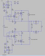
The original patent seems to only N-FDBK control the driver currents, not the output device currents. Massively parallel outputs required to avoid thermal issues.
Looks like the tube version only controls the bias V for the Mosfets too. So massive overkill needed for the output devices again (to avoid thermal/bias issues).
With 300 Amp 800 Watt Mosfet industrial motor control modules (something like 0.02 uF input C), driven by a wimpy EC86 follower, the slew rate issues must be problematic to say the least.
Last edited:
The original patent seems to only N-FDBK control the driver currents, not the output device currents. Massively parallel outputs required to avoid thermal issues.
Looks like the tube version only controls the bias V for the Mosfets too. So massive overkill needed for the output devices again (to avoid thermal/bias issues).
With 300 Amp 800 Watt Mosfet industrial motor control modules (something like 0.02 uF input C), driven by a wimpy EC86 follower, the slew rate issues must be problematic to say the least.
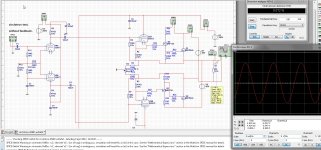
I did ask myself why such a big mosfet with uge Cn can be driven by a small tube and keep bandwidth intact. I did read she use a singe mosfet module of very high amperage, these has also big capacitance, far in the Nanofarad.
So the trick has to be quick discharge by the gate source resistor, that this amp sound good, I move to some doubt because of the load of the driver tubes, I have done a extra mosfet driver then power mosfets now I can drive these modules, maybe however the circlotron do because it floates between supply.s can discharge fast.
last picture I did a while ago, until I did see now the rem amp. here I have use mu outputs in the voltage amp section/fase shifter quite low distortion with 100 watts output class a idle so not real in AB.
Attachments
Last edited:
- Status
- This old topic is closed. If you want to reopen this topic, contact a moderator using the "Report Post" button.
- Home
- Amplifiers
- Tubes / Valves
- Thorens TEM 3200 clone