Hello
My Frend have one and dont have a trafo or power supply.
Someone maybe know that what is the voltage for power preamplifier.
Preamplifier have 4 contact for power suplly, and i dont have circuit diagram or rectifier because i dont know what is the voltage.
please help
thanks
My Frend have one and dont have a trafo or power supply.
Someone maybe know that what is the voltage for power preamplifier.
Preamplifier have 4 contact for power suplly, and i dont have circuit diagram or rectifier because i dont know what is the voltage.
please help
thanks
You will have to use 2 x 15VAC transformer with split secondaries = 4 wires (not the one with center taped - 3 wires) if the preamp uses 2 diode bridges for convetring AC to DC. Math...15VAC x 1.41 = 21,15VDC....21,15VDC - 2 x diode voltage drop (depends on current draw and type of diodes used in diode bridges) = ~19,65VDC so you will have ~4,65VDC difference from input to output of LM7815/7915 as they need Vdrop=2VDC min. for proper operation.
Thanks but
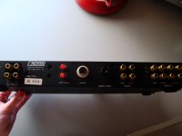
Preamp on the back side have 3 wires ( one wires to 1 leg of 7815 , another leg to 7915 and 3 leg for the central ground ) for power supply and dont have any rectifier inside
in orginal power supply ( another box that my frend dont have ) have rectifier and trafo and nothing else
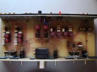
i build power supply whit trafo 9,7-0-9,7 AC for test only and preamp work but dont have sound because relay on the output is 24V ( 2 pieces ) and on the output opamp ( ne5534 ) leg 7 voltage is 1V
relay is not working because voltage is to small
here is picture
Preamp on the back side have 3 wires ( one wires to 1 leg of 7815 , another leg to 7915 and 3 leg for the central ground ) for power supply and dont have any rectifier inside
in orginal power supply ( another box that my frend dont have ) have rectifier and trafo and nothing else
i build power supply whit trafo 9,7-0-9,7 AC for test only and preamp work but dont have sound because relay on the output is 24V ( 2 pieces ) and on the output opamp ( ne5534 ) leg 7 voltage is 1V
relay is not working because voltage is to small
here is picture
Attachments
You could make voltage doubler circuit and use the transformer you already have if VA rating is sufficient. Also, you will have to watch a dissipation over LM7815/7915 since in case of voltage doubler circuit, output voltage will be 2 x (9V7 x 1,41) - voltage drop over diode bridge = ~ 26VDC. Furthermore, you could use RCRCRC filtering after voltage doubler circuit to drop some volts before LM7815/7915 in order to lessen dissipation.
You will need a trafo 15-0-15 if You want 7815 and 7915 to work as they should. For the relays as u said they are 24V. I think You should follow the power supply input pins where they lead. According me You will need another voltage for relays, separated from those for 7815 and 7915.
thanks
by lm7815 and 7915 is elko 1000uF/25V and i dont whant to change this parts")
OK, then measure current draw from LM7815/7915 (probably few tens on mA, say 50mA). Now, since you will have ~26VDC after voltage doubler, and you want, >/=18VDC in front of LM7815/7915, just stick a resistors of (26-18)/50mA = 160R or so in series between voltage doublers and LMs. Now, you will have RC filter with your treasured vintage capacitors, and less dissipation over LM's.
- Status
- This old topic is closed. If you want to reopen this topic, contact a moderator using the "Report Post" button.
- Home
- Source & Line
- Analog Line Level
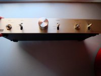
- Thorens restec V1 preamplifier