Nuuk said:I have just uploaded the first version of my Gainclone page to Decibel Dungeon but there is no internal link to it as yet.
It can be viewed HERE
Nice... a little lighter background would be nice (black on dark blue is kinda hard to read). You could also give me credit for drawing of the scematic -- i would be happy to make you a suitable gif version of it -- jpg is not a good format for line drawings and degrades the quality of the image.
dave
Hi Dave, so you are the originator of that schematic. I'll be happy to put an acknowledgment up to that effect (what's your full name?) and if you do have a gif file, that would be welcome!
As regards, the black text, it should be light blue if you are using a recent browser that handles CSS.")
As regards, the black text, it should be light blue if you are using a recent browser that handles CSS.
Nuuk said:Hi Dave, so you are the originator of that schematic. I'll be happy to put an acknowledgment up to that effect (what's your full name?) and if you do have a gif file, that would be welcome!
As regards, the black text, it should be light blue if you are using a recent browser that handles CSS.
Nick,
My browser shows white on deep blue
nice page, and easy to read. It is only after reading your page that I understand how you were able to make these beautiful wooden "cases" for your clone.
B.t.w. thanks for including me in your links, can I help you with a better link to my site perhaps?
Maarten
Nuuk said:so you are the originator of that schematic. I'll be happy to put an acknowledgment up to that effect (what's your full name?) and if you do have a gif file, that would be welcome!
David Dlugos (and if you could link my name to my website). I'll work a gif up for you, mail me so that i have an email to reply to with an attachment.
As regards, the black text, it should be light blue if you are using a recent browser that handles CSS.
A recent browser, but no support of CSS (iCab) -- i haven't found a CSS compliant browser anywhere near as useful as the one i'm using (they promise full CSS in the next major revision). As opposed to the hundreds of programmers working on the fatties, there are 1.5 guys working on this one.
dave
planet10 said:jpg is not a good format for line drawings and degrades the quality of the image.
Depends how much compression you use for the JPG. At 100% quality a JPG looks just as good as a GIF. Though the file size is larger for the JPG than for the GIF. And if you apply enough compression to the JPG to make it the same size as the GIF, it does look really ugly.
se
help please.
just finished my first channel of my gainclone using an OPA548. i used the datasheets to get the pin layout and i have triple checked my connections.
the problem is, i get -v on my output. this voltage is equal to my supply voltage (20v) im lucky my speaker was disconnected. my heatsink is at -20v but its not touching anything. the current limiter pin is connected to -v.
can anyone suggest anything i can do/check?
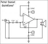
Matttcattt said:here is the circuit i am using.
Where did you get that?
That's an edited version of the one I did for Peter for the LM3875. Whomever edited it has the + and - inputs on the amp reversed and the pinouts on that schematic do not match the pinouts on the OPA548.
se
David Dlugos (and if you could link my name to my website).
Sure Dave, consider it done!
I would much rather support some of the smaller software producers but compatabilty is always an issue, especially if I want to use techniques like CSS. I wonder if we will ever have a standard for such issues as web browsers?
B.t.w. thanks for including me in your links, can I help you with a better link to my site perhaps?
Sure Maarten, just let me now what you want and I'll put it in there.
BTW - a long day eh?

MatttCattt, just checked out the data sheet and the OPA548 has the metal tab tied internally to V-, so you need to isolate the case from the heatsink unless you want your heatsink at -V which isn't a good idea.
And the difference between the pinouts of the schematic you gave versus the OPA548 should be changed to the following:
Pin 1/Pin 5
Pin 3/Pin 6
Pin 4/Pin 4
Pin 7/Pin 1
Pin 8/Pin 2
Where Pin/Pin = LM3875/OPA548.
Check your wiring against this.
se
And the difference between the pinouts of the schematic you gave versus the OPA548 should be changed to the following:
Pin 1/Pin 5
Pin 3/Pin 6
Pin 4/Pin 4
Pin 7/Pin 1
Pin 8/Pin 2
Where Pin/Pin = LM3875/OPA548.
Check your wiring against this.
se
Steve Eddy said:At 100% quality a JPG looks just as good as a GIF.
A jpg even at 100% will still have some artifacts. And you are right, it will be WAY bigger.
Steve Eddy said:Where did you get that?
That's an edited version of the one I did for Peter for the LM3875.
Which must have been an edited version of mine
dave
gainclone with pga2310
For a school project, I am going to make a digitally controlled amplifier with a burrbrown pga2310 and a lm3875 chips. When using the lm3875 in inverted configuration with the pga2310, would it be advisable to put a 50k resistor to ground, where the pot should be?
Also, my analog professor says that it would be better to use the lm3875 in non-inverted configuration, since the input resistance doesn't effect the gain, and there is more bandwidth with the non-inverted configuration. Has anyone done a direct comparison of the two configurations?
--
Brian
I was experimenting with my monoblocks yesterday and adding 50k input to ground resistor didn't really change anything, so you may leave it out.
As to bandwith, I checked my inverted LM3875 and measured frequency response 5Hz-1Mhz +/-.3db with 50k pot at the input at full volume. At volume at 3 oclock pos it was up to 300kHz.
I didn't have a chance to compare inverted to non inverted config.
As to bandwith, I checked my inverted LM3875 and measured frequency response 5Hz-1Mhz +/-.3db with 50k pot at the input at full volume. At volume at 3 oclock pos it was up to 300kHz.
I didn't have a chance to compare inverted to non inverted config.
planet10 said:A jpg even at 100% will still have some artifacts. And you are right, it will be WAY bigger.
There don't appear to be any artifacts for a simple line drawing.
Here's the GIF:
<center>
<img src="http://www.q-audio.com/images/shapes.gif">
</center>
And here's the JPG:
<center>
<img src="http://www.q-audio.com/images/shapes.jpg">
</center>
Both of these were created separately, sourced from the same vector-based drawing (via CorelXARA!).
Even when zoomed in, I can't spot any differences between the two.
The GIF is 4K and the JPG is 13K.
Here's the JPG at 50% quality (6K):
<center>
<img src="http://www.q-audio.com/images/shapes2.jpg">
</center>
At 25% quality (5K):
<center>
<img src="http://www.q-audio.com/images/shapes3.jpg">
</center>
And at 0% quality (3K):
<center>
<img src="http://www.q-audio.com/images/shapes4.jpg">
</center>
Oops. I seem to have had transparancy turned on for the GIF. But trust me, when you look at it on a white background, it's indistinguishable.
Which must have been an edited version of mine
Ah. Hehehe. Thought that was Peter's drawing.
Well, at least I didn't swap the + and the - on the input.
se
Re: gainclone with pga2310
No. Leave that out. The pot's only there for attenuation which you'll be providing via the 2310. The input impedance will be the value of the series resistor, in this case, 10k. You can make it lower if you like. The 2310 (a functional equivalent of the Crystal CS-3310) can drive a 600 ohm load. Just be sure to scale the feedback resistor appropriately if you do.
se
BrianGT said:For a school project, I am going to make a digitally controlled amplifier with a burrbrown pga2310 and a lm3875 chips. When using the lm3875 in inverted configuration with the pga2310, would it be advisable to put a 50k resistor to ground, where the pot should be?
No. Leave that out. The pot's only there for attenuation which you'll be providing via the 2310. The input impedance will be the value of the series resistor, in this case, 10k. You can make it lower if you like. The 2310 (a functional equivalent of the Crystal CS-3310) can drive a 600 ohm load. Just be sure to scale the feedback resistor appropriately if you do.
se
Steve Eddy said:There don't appear to be any artifacts for a simple line drawing.
They are there, but they are subtle.
dave
Steve Eddy said:
Where did you get that?
That's an edited version of the one I did for Peter for the LM3875. Whomever edited it has the + and - inputs on the amp reversed and the pinouts on that schematic do not match the pinouts on the OPA548.
se
i found it on this tread, i changed the inputs but forgot to edit the pin numbers
Steve Eddy said:MatttCattt, just checked out the data sheet and the OPA548 has the metal tab tied internally to V-, so you need to isolate the case from the heatsink unless you want your heatsink at -V which isn't a good idea.
And the difference between the pinouts of the schematic you gave versus the OPA548 should be changed to the following:
Pin 1/Pin 5
Pin 3/Pin 6
Pin 4/Pin 4
Pin 7/Pin 1
Pin 8/Pin 2
Where Pin/Pin = LM3875/OPA548.
Check your wiring against this.
se
my gainclone is just a test so the heatsink at -20v is ok.
i have checked my wiring and it is correct.
(sighs) ive been looking at the data sheet of the 7824 and it shows a circuit for a current boost regulator (so it can handle a higher current) but i do not understand it all - it uses a resistor to define the turn on of the pnp transistor...(looks confused) i dont understand why its needed - the pnp transistor needs to be on all the time?
- Status
- This old topic is closed. If you want to reopen this topic, contact a moderator using the "Report Post" button.
- Home
- Amplifiers
- Chip Amps
- This is not just another gainclone