CBDB:
You're welcome, but more recently Mightydub has been doing most of the work. I started the wiki and wrote the beginning material, but since then there have been contributions and edits by several people. I haven't found time to edit in my most recent information.
Where did Andy go? It would certainly be hard to replace him.
- keantoken
Then thanks to mightydub also. There as an entire thread on Andy_C's banishment. I didnt read it all but the jist was he was unhappy about something (maybe some else knows what) so he went out of his way to be rude and offensive (I have never seen him that way before ). He was one of the few real experts on this site and most of all he was more than happy to share his experience and knowledge, no matter how dumb the question and never condescending. (unlike some of the so called experts, one especially comes to mind). He will be sorely missed.
re Laplace, check the Yahoo group, I did a quick scan and there are several files and questions/answers there.
Andy_c (or someone with that handle) is over at www.diy-audio-engineering.org. I haven't read the thread, but I'm sad that he has departed, seemed like he really knew his stuff.
I hope that people have found the LTspice wiki useful, lately I've been too busy to contribute anything but hope to get back to my various audio projects soon.
Last edited:
Yes its Andys new website. And some of the more technically savy members from here are joining in. hes trying to keep it more engineering and less audiophool. the catch is you sorta have to apply for entry.(to keep out the commercial interest and there slanted views). for more info go here:
What's the forum all about?
What's the forum all about?
Hello
I've found a model for the ntp60n06 mosfet.
I want to use it with LTspice, but there is few models sections in the same file: .MODEL MM NMOS .MODEL MD D .MODEL MD1 D .MODEL MD2 D
.MODEL MD3 D
Do I use all of those or some parts of them ?
Here is the complete file, which parts of it I should take to do a ntp60n06 LTspice model, is somebody can edit this model file so I can use it with LTspice ?
Thank a lot
Bye
Gaetan
Attachments
Last edited:
see the top line in the file : .subckt
Took me a minute to find it, usually it follows the commented section. Subcircuits provide for hierarchy so the behavior of a single symbol can be represented by an arbitrarily complex spice netlist.
See post #125 above, the help file, and/or the yahoo LTspice group for details on how to use subcircuits.
Run an AC analysis, left click on the trace name, and drag the crosshairs over the desired point you want to know the phase shift at. If the phase isn't plotted, click on the right edge of the graph and deselect "don't plot phase". If it doesn't make sense, toggle the "unravel branch wrap" option.
- keantoken
- keantoken
check the Yahoo group (you do have to register) - and then search - we really, really like people who can search, find examples in the files section there
there are examples with .meas that work on .tran waveform zero crossings that print out the results in the log file
also after an .tran you can view the fft - using a cursor on each waveform you can measure relative phase of any pairs of frequency components
there are examples with .meas that work on .tran waveform zero crossings that print out the results in the log file
also after an .tran you can view the fft - using a cursor on each waveform you can measure relative phase of any pairs of frequency components

fair enough , but there are other groups who makes the library and unfortunately i downloaded many library and none of them had sg/lm 3524 regarding national semi conductor , no man they are not giving any detail , the only library they are providing are audio opamp seeh it's complicated
Generally for the mixed mode (analog plus digital/behavioral) models, Linear Tech seems to be the only company that cares to create and publish models for LTspice. You should have a look at the Yahoo LTspice group, I did a quick check, is this: http://f1.grp.yahoofs.com/v1/wMGKTZ...V_L-2e6PYphHq6D_ofvIf7BQnxJJARMT/swit_reg.lib what you are looking for?
Alternative path, go to http://tech.groups.yahoo.com/group/LTspice/files/ and look at the link at the bottom of the page.
The Yahoo LTspice group is an amazing resource.
Alternative path, go to http://tech.groups.yahoo.com/group/LTspice/files/ and look at the link at the bottom of the page.
The Yahoo LTspice group is an amazing resource.
Kean! I need your help!
I am trying to sim a simple common source fet cascode in LT spice. No matter what I do, I always get increased distortion with a cascode when compared to a non cascoded circuit.
Am I doing something wrong, or could this possibly be because the models don't properly account for changes in gain and input capacitance with current, voltage and frequency? If this were the case, a cascode would model worse than a non cascoded circuit as it is the influence of exactly these things that a cascode reduces.
Have you been able to successfully model a cascode in lt spice?
I am trying to model a cascode using two irfp240s and a resistive load as a proof of concept. I have a 80v rail voltage and the cascode voltage is 15v. So far distortion of the cascoded circuit is always about double the distortion of the simple common source amplifier. I have no idea why. Even if I use BJTs I get a similar result.
If you are using Cordell's models (he has the IRF240/9240), you should be safe.
All transistors become more linear with increasing collector/drain voltage (distortion can be induced by modulating Vds. In bipolars this is called Early effect). By lowering this voltage you may degrade performance. If your cascode FET is just acting like a supply rail, it's Vgs distortion will be added to the Vds distortion of the follower FET.
There are a few tricks often used with cascodes, that will affect the diagnosis, so it will make this easier if you post your schematic. Then I can probably make a detailed explanation.
- keantoken
Jed,
I have tried but got spurious results (never ending simulations).
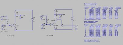
Kean, here is an example I whipped up using the included models in LT spice. It does not matter whether I use BJTs or Fets, or what my cascode voltage is. I can not get cascodes to sim better, full stop. Either I am doing something wrong or the models do not account for miller effects, etc. Help!
I have tried but got spurious results (never ending simulations).
Kean, here is an example I whipped up using the included models in LT spice. It does not matter whether I use BJTs or Fets, or what my cascode voltage is. I can not get cascodes to sim better, full stop. Either I am doing something wrong or the models do not account for miller effects, etc. Help!
Attachments
First of all, LTSpice compresses the output data by default, and this will destroy any distortion measurements. To turn this off, add this line:
.options plotwinsize=0
Now try again. Hmm, maybe you just forgot about this?
After that, try deleting the 1k base resistors; these will add distortion to your circuit in ways that may be misleading if you do not understand well what effect they have.
Finally, you could very understandably delete all of the default LTSpice models (which are copies of vendor models anyways and just as bad) except perhaps the MPSA18 and 2N4124/4126 (very good transistors), and just use the models from Cordell's website, which are guaranteed to model accurately. Cordell has BC550/560 models which are basically equivalent to your BC546, just with less Hfe (which can be altered in Cordell's models and still probably do better than the LTSpice defaults).
CordellAudio.com - SPICE Models
Also check here for good models (but you may have to look around for the latest versions).
Simulation Tools
Finally, I suspect the reason you have not done all this already is because perhaps you are a bit overwhelmed. This is ordinary and common. Just ask and I can give you easy instructions.
- keantoken
Hello
I would like to simulate a Intermodulation distortions test using 5 signal.
Any ways to do it with the most realitic result possible ?
I include an asc file of one of my amps, so you could use it to give me any suggestions.
Thank
Bye
Gaétan
I would like to simulate a Intermodulation distortions test using 5 signal.
Any ways to do it with the most realitic result possible ?
I include an asc file of one of my amps, so you could use it to give me any suggestions.
Thank
Bye
Gaétan
Attachments
Last edited:
- Status
- This old topic is closed. If you want to reopen this topic, contact a moderator using the "Report Post" button.
- Home
- Design & Build
- Software Tools
- Things you should know about LTSpice