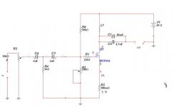
Hi ,Bogdan, very nice SE amp, can we get the parameters of inductor?
I have built a similar your amplifier ,the schematics
from forum,the voice like the tube sound,very good!
Best regards!
120mH / 0.9 Ohms
Hi Bogdan,
What happened to this amp? I thought it very good...... have you progressed the production of this amp for sale?
Hugh
Yes, it sounds beautiful. I`ve made a change to bjt driver instead of mosfet, and switched to TPC. The sound is better. Amplifier is alive and well playing at my friends home .
")
Have I said something about "production of this amp for sale"?
 You can sand me PM...
I'm building an inductively loaded SE amp too.
Inductor information:
100mH, 4A quiescent, 0.47R DCR, 1.5mm wire, 4Kg (8.8lbs), GOSS laminations, gapped around 5 thou. I had two custom built (around $USD175 each!) but yet to gap them with a good friends' gear in a couple of weeks.
If you use a CCS rather than an inductor the efficiency is almost halved. I'm expecting 54Vpp output from a 36Vdc supply, which into 8R is around 45W. From experiences with another SE amp I build in the nineties the sound will be utterly transparent; THD from LTSpice indicates it will be 0.002% at 45W, and the same at 1W. My design is much simpler than Bogdan's amp, but the output design will use 2 x FQA36P15 trenchfets from Fairchild. I have a stash of these devices which have a Pd of 280W. Front end will be tube. Thermal issues are paramount; I will be using a slow speed 120x120 fan blowing up into a tower of heatsinks. This is a love project, not a commercial product. I cannot imagine selling this with 300W heat and 2 x 45W output.
Cheers,
Hugh
Last edited:
Yes Hugh, I think that your concept with "Glass harmony" amp - tube gain stage and cfp choke loaded follower should sound better and you don`t need the GNFB. The Pathos amp used that concept as well, but with plan source follower and IMO wrong type of tubes (12AX7) . What tube you plan to use?
Hi Borko,
I've almost forgotten the Glass Harmony, but I've begun another, with more power. I think your design is very, very good and from my experience of topologies I'm absolutely convinced it will be wonderful to listen to. Yes, the 12AX7 is not the best tube for the Pathos; it has only 1.2mA plate current, not enough to drive a gate. And I understand from a good friend that the mosfets run at around 60C and fail each two years.
Thank you for sharing your circuit!
Cheers,
Hugh
You betcha Wahab,
The predominating H2 with linear reduction of harmonics is the hallmark of the Class A SE.
But you knew that...... I have just received a box of magnetics and now I have to fix the pcb design. Keeping the beast is tricky; I will be using a 120x120 fan at 1500rpm and very narrow finned heatsinks.
The price to pay is the huge heat dissipation, and relatively low power output. THD is actually not very low.
Hugh
Hugh
Member
Joined 2009
Paid Member
Holy cow Hugh, do you need so much power in SE !?
OK - I'm jealous, it sounds a lot of fun !
I'm listening to a single tube right now, a little 9-pin russian tetrode running off around 230V at the plate and 30mA or so. It's the gain stage and output stage all by itself. Yet I can't turn up the volume or my family complains !
OK - I'm jealous, it sounds a lot of fun !
I'm listening to a single tube right now, a little 9-pin russian tetrode running off around 230V at the plate and 30mA or so. It's the gain stage and output stage all by itself. Yet I can't turn up the volume or my family complains !
Gareth,
About 15 years ago I built a 55W SE mosfet with 6SL7 input stage. Quiescent was 4.2A, 70V on the rail, AND WATER COOLED.
It used a total loss water cooling principle, needed a domestic water output, expelled onto the house lawn.
Predicably, my eldest who was 15 and infatuated with her pop music, switch it on one day but did NOT turn on the water.
My masterpiece immolated in a few minutes. I cried for days, my relationship with my eldest, Soraya, is strained to this day.
O my golly, I've had a wonderful story with audio...... I've just been weeping for joy watching Jay Leno taking his 2.6 1932 straight 8 Alfa Romeo for a spin. Last night my brother rang to tell me he has bought a W800 Kawasaki, a classic, to pair with his Z1400 Concours. I just bought a Ford Focus with the hotrod DW diesel - all this love of machinery and audio is in the blood.
45W is almost earth shattering, but as you know, with SE 1W is too much and 100W is not enough.
Hugh
You betcha Wahab,
The predominating H2 with linear reduction of harmonics is the hallmark of the Class A SE.
But you knew that...... I have just received a box of magnetics and now I have to fix the pcb design. Keeping the beast is tricky; I will be using a 120x120 fan at 1500rpm and very narrow finned heatsinks.
The price to pay is the huge heat dissipation, and relatively low power output. THD is actually not very low.
Hugh
Hugh
Hi Hugh,
Distorsion is really not a problem here since it s 0.01% at most at 1KHz and no more than 0.05% at 10KHz, much less the 60W (per channel) dissipation, but given the topology it can be fed with 18V and still be within HiFi specs power wise (DIN 45500 sort of...) with only 25-30W thermals..
Anyway have fun with your build, thoses designs are rather electromechanics than electronics, and somewhat of a tubish concept...
You betcha Wahab,
The predominating H2 with linear reduction of harmonics is the hallmark of the Class A SE.
But you knew that...... I have just received a box of magnetics and now I have to fix the pcb design. Keeping the beast is tricky; I will be using a 120x120 fan at 1500rpm and very narrow finned heatsinks.
The price to pay is the huge heat dissipation, and relatively low power output. THD is actually not very low.
Hugh
Hugh
Hugh, I think it`s better to invest in a larger heatsinks and lover the voltage for fans to get a lower rpm. I already tried something like that, and I think you will hear the fans and air flow at this speed and rise the noise floor of your room at quiet nights.
Hi Borko,
Good advice.
However, I used a Conrad MF18, played a 120x120mm fan at 1500rpm through it, and dissipated 175W at an ambient rise of 27C. It was a heatwave in Melbourne at that time, and the day temperature was 42C at 5pm. The heatsink was at 67C, dropping to 52C during the night when the ambient dropped to 25C. I'm planning to drop 140W across each heatsink (two, facing fins with a fan below driving air through) and I realise the biggest noise will the turbulent as the rotating airflow passes to the fins. I will need to use a plenum, I think, to remove the proximity between fan and fins.
It should be OK, but I will let you know..... right or wrong!!
Thanks for your interest, it's a big project; I'm finalising the SS/tube pcb design, it's quite a lot of work to get the layout correct.
Cheers,
Hugh
Yes, it sounds beautiful. I`ve made a change to bjt driver instead of mosfet, and switched to TPC. The sound is better. Amplifier is alive and well playing at my friends home .
Have I said something about "production of this amp for sale"?
Hi Bogdan,
Can you please share the bjt driver version of this schematic? I`m bery interested. Next year i'll buy some copper and trafos for the 120mH coils.
Thanks in advance.
Happy new year!
Cheers
Sergiu
Hi Borko,
Good advice.
However, I used a Conrad MF18, played a 120x120mm fan at 1500rpm through it, and dissipated 175W at an ambient rise of 27C. It was a heatwave in Melbourne at that time, and the day temperature was 42C at 5pm. The heatsink was at 67C, dropping to 52C during the night when the ambient dropped to 25C. I'm planning to drop 140W across each heatsink (two, facing fins with a fan below driving air through) and I realise the biggest noise will the turbulent as the rotating airflow passes to the fins. I will need to use a plenum, I think, to remove the proximity between fan and fins.
It should be OK, but I will let you know..... right or wrong!!
Thanks for your interest, it's a big project; I'm finalising the SS/tube pcb design, it's quite a lot of work to get the layout correct.
Cheers,
Hugh
Hi Hugh,
Thanks again for the help with my Hiraga amp. I am really enejoying it now. How is your chocke loaded amp project going?
Cheers
Sergiu
Tragically, Sergiu, I have not yet finished it........ but I have all the iron and need only to take a deep breath and put in the smd 12106 on the small pcb to finish the 'electronics', ahem.....
So glad your Hiraga is running well, I learned a lot from Jean Hiraga those years back, and even today I marvel at how they sound so well using a symmetrical design!
Happy New Year to you and other audio tragics!! Quelle Horreur!
Hugh
So glad your Hiraga is running well, I learned a lot from Jean Hiraga those years back, and even today I marvel at how they sound so well using a symmetrical design!
Happy New Year to you and other audio tragics!! Quelle Horreur!
Hugh
- Status
- This old topic is closed. If you want to reopen this topic, contact a moderator using the "Report Post" button.
- Home
- Amplifiers
- Solid State
- TheTwelve SE class A TMC amplifier