I mean the LTSpice schematic. I noticed that you've gone through several iterations and would like to see your latest and greatest. The THD numbers on your circuit are outstanding.
In particular your JFET input stage and VAS topology are very interesting. The use of ThermalTrak makes this a very nice amplifier design!
How does your prototype sound? Have you designed a PCB?
/Mason
Here is zip file with two .asc files and transistor models used. Just unzip it in the same directory and run a simulation(of course you have to have LTspice software).
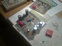
You can see PCB in post #27, it is not the last one as I am trying to improve it on the go.
I was listening to the amp(version III) as you ca read in this thread and I was very satisfied with the sound even with basic power supply. I intend to make better power supply with electronic protection incorpored.
dado
Attachments
Hi
Sometimes in these threads the same problems come around and around ...
one reason Self's slew rates were asymmetrical was because of the CCS in the VAS stage. The trouble is with the resistor in series with the base, in dadod's circuit it is R38. This seems to have been a derivative of an old RCA circuit (used in their hybrid circuit HC1000) but was always a cheap fix to the problem of the CCS shorting the current source to the input stage if it were to saturate. Far better to use two reference diode chains and separate the bases of the CCS and the CCS for the input stage.
I suppose that you talked about first schematic in this thread. I changed CCS latter but still use base resistor(100ohm). Please look at latest schematics and tell me how to improve CCS. Diode string instead transistor is better according to you??
Although Cherry pointed this out, as well, dadod has a capacitor across the base of the CCS which offsets the speed issue to some extent. But parasitic capacitances on the base of a transistor can sometimes lead to oscillations. Better to use a low impedance (low resistance) - say less than 50 ohms - as might be provided by two forward biased diodes.
I don't use a capacitors across the base any more.
As for the VAS stage, the use of 2.2 ohm resistor is curious. To improve the slew rate it is necessary to use greater local feedback (10 ohms or more) or, preferably, to use cascodes in the VAS stage. Most VAS stages even with emitter resistors of 10 ohms or so do not seem to be able to offer the speed improvement nor linearity improvement of a cascode. Most distortion seems to arise in the VAS given other stages are optimised, and with the traditional VAS this is not satisfactorily addressed. Cascodes on the other hand offer at least double the frequency performance, and reduce Early effect distortion to negligible proportions.
DOn't know whether this helps at all, but maybe some of the old problems won't keep going round...
John
I use 15ohm as VAS degeneration now. I tried higher but distortion increased. I tried cascoded VAS( Hawksford cascode ) but no improvement in distortion, and VAS would need higher voltage. I desided to use VAS buffer insead(emitter follover).
Please comment, as I would appreciate help here.
All tests were done in simulation for the moment.
dado
While I agree with john ellis that the emitter resitor should be a bit higher in value (max 33 ohms) the effects of vas loading should be kept in mind and this resistor is main contributor and should be kept small, 15 to 22 ohms is good.
Cascoding the vas brings such minor advantage it could be said it relates to zero, this in light of vas loading. It has even less effect when beta enhancer is used before the vas. To lower THD without too much hassle is to rather connect the collector leg of the beta enhancer to opposite rail instead of ground, this will lower early effect if your transistor can handle it. Even better is to lower the vas output impedance by using a small geometry mosfet as the beta enhancer or the use of a superbeta transistor or even a darlington here. Cascoding the vas will show more improvement if the vas is a darlington or a super beta type but rather vas buffer or the use of mosfets as driver is the better way to go.
Cascoding the vas brings such minor advantage it could be said it relates to zero, this in light of vas loading. It has even less effect when beta enhancer is used before the vas. To lower THD without too much hassle is to rather connect the collector leg of the beta enhancer to opposite rail instead of ground, this will lower early effect if your transistor can handle it. Even better is to lower the vas output impedance by using a small geometry mosfet as the beta enhancer or the use of a superbeta transistor or even a darlington here. Cascoding the vas will show more improvement if the vas is a darlington or a super beta type but rather vas buffer or the use of mosfets as driver is the better way to go.
While I agree with john ellis that the emitter resitor should be a bit higher in value (max 33 ohms) the effects of vas loading should be kept in mind and this resistor is main contributor and should be kept small, 15 to 22 ohms is good.
Cascoding the vas brings such minor advantage it could be said it relates to zero, this in light of vas loading. It has even less effect when beta enhancer is used before the vas. To lower THD without too much hassle is to rather connect the collector leg of the beta enhancer to opposite rail instead of ground, this will lower early effect if your transistor can handle it. Even better is to lower the vas output impedance by using a small geometry mosfet as the beta enhancer or the use of a superbeta transistor or even a darlington here. Cascoding the vas will show more improvement if the vas is a darlington or a super beta type but rather vas buffer or the use of mosfets as driver is the better way to go.
Thank you for your comments, I agree with them but use of small mosfet as a beta enhancener, to high input capacitance(or I don't know any with low).
Damir
Dadod look at Zetex range, you should find some there with below 80 pf gate capcitance. It would be better if it were N channels you needed. THD at frequencies below about 5 khz will be lower anyhow and only above that would you see any increase in THD if at all. Keep Vds as large as possible by connecting opposite rail and not ground.
You can see PCB in post #27, it is not the last one as I am trying to improve it on the go.
Please share the bottom layer silhouette when you have it finalized. I'm definitely interesting in etching my own board!
Thanks,
Mason
Please share the bottom layer silhouette when you have it finalized. I'm definitely interesting in etching my own board!
Thanks,
Mason
OK, I have to rechack layout and then I will show PCB and the scematic.
dado
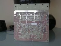
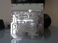
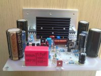
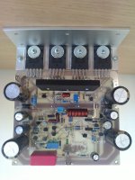
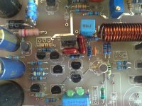
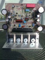
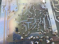
With Mason help we double checked the PCB layout and now I show three wersion of the TT amp.
First here is full version with TRIPLE output and buffered VAS. Schematic attached and the PCB layout, PDF inverted bottom layer(for hot iron method) and PDF layer for standard photo development.
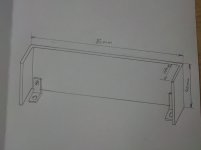
Also shoved home made drivers heathsink.
There some jumpers to be inserted and transistor not to be populated:
1. DADO-TT-triple-bufferedVAS
Not to be populated:
Q20, R50
Jumpers to be inserted:
ALL X, J3
dado
First here is full version with TRIPLE output and buffered VAS. Schematic attached and the PCB layout, PDF inverted bottom layer(for hot iron method) and PDF layer for standard photo development.
Also shoved home made drivers heathsink.
There some jumpers to be inserted and transistor not to be populated:
1. DADO-TT-triple-bufferedVAS
Not to be populated:
Q20, R50
Jumpers to be inserted:
ALL X, J3
dado
Attachments
Now this amp is possible to have with standard EF output stage and not losing to much of the performance, distortion is not much worse and buffered VAS compensate for one less stage(predrivers).
3. DADO-TT-EF-bufferedVAS
Not to be populated:
Q20, R50, Q19, Q21, R40, R47, R41
Jumpers to be inserted:
All X, J3 or J4, J5, J6
*******
C24 and C19 to be soldered from backside directly on transistor legs
J3 is DM3135 from Supertex, R42 will have different value then showed on the scematics
dado
3. DADO-TT-EF-bufferedVAS
Not to be populated:
Q20, R50, Q19, Q21, R40, R47, R41
Jumpers to be inserted:
All X, J3 or J4, J5, J6
*******
C24 and C19 to be soldered from backside directly on transistor legs
J3 is DM3135 from Supertex, R42 will have different value then showed on the scematics
dado
Attachments
Very nice, dado!
I'm looking forward to seeing your build and listening interpretation! This is an excellent design.
Is 'AudioCube' the official name?
/Mason
Hi Mason,
I think I stick with this name as I intend to build two amp boxes in a cube shape with three channel in each one.
dado
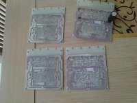
Those boards look good, which version of the amp is built on to it ??
All three version described in the posts before, configurated with a jumpers.
dado
Power Supply
Here is the link to the Power Supply I intend to use for this amp, for the moment simulated only. I used some ideas from JLH 80W MOSFET amp's power supply.
http://www.diyaudio.com/forums/powe...iplier-electronic-protection.html#post2901733
dado
Here is the link to the Power Supply I intend to use for this amp, for the moment simulated only. I used some ideas from JLH 80W MOSFET amp's power supply.
http://www.diyaudio.com/forums/powe...iplier-electronic-protection.html#post2901733
dado
Power Supply
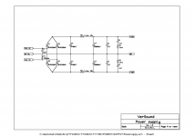
This is power supply I will use with TT amp.
First schematic is main power supply with fast diodes and big electrolytic capacitors.
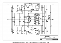
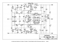
Next are two schematics of a regulator and protection part, one with MOSFET regulator and one with BJT regulator.
The regulator part acts as capacitor multiplier, electronic fuse and loudspeaker protector, all in one.
Electronic fuse will act after some threshold set by series resistor(0.11ohm in this case) and with a delay, smaller toward higher current.
Loudspeaker protection will be trigered if DC voltage persists on power amp output. This is controled with 1Mohm resistor and 2.2uF capacitor.
I did not get any comment or suggestion for improvements on the power supply thread, so I hope, here I get some responce.
dado
This is power supply I will use with TT amp.
First schematic is main power supply with fast diodes and big electrolytic capacitors.
Next are two schematics of a regulator and protection part, one with MOSFET regulator and one with BJT regulator.
The regulator part acts as capacitor multiplier, electronic fuse and loudspeaker protector, all in one.
Electronic fuse will act after some threshold set by series resistor(0.11ohm in this case) and with a delay, smaller toward higher current.
Loudspeaker protection will be trigered if DC voltage persists on power amp output. This is controled with 1Mohm resistor and 2.2uF capacitor.
I did not get any comment or suggestion for improvements on the power supply thread, so I hope, here I get some responce.
dado
Attachments
- Status
- This old topic is closed. If you want to reopen this topic, contact a moderator using the "Report Post" button.
- Home
- Amplifiers
- Solid State
- ThermalTrak+TMC amp