haha yeah well that'll do it. i admit I wasnt looking for something so obvious after the last issue. i would also suggest to try to remove some of the excess solder on your joints, overall there is far too much. in particular there is a blob on one of the power supply decoupling caps on the amp board underside
definitely clean off the one i circled with the ? and note or you will probably end up with the soldermask breaking down and causing a short. do this before you power up again
definitely clean off the one i circled with the ? and note or you will probably end up with the soldermask breaking down and causing a short. do this before you power up again
Attachments
cool!! no probs, did you get some of that solder off the decoupling caps i pointed at in the pic above? if you dont its likely to eventually short through the soldermask and die
yeah part of the cool thing about most opamps is they dont have a ground connection, so you can escape shorts etc sometimes if you catch it in time. did you have to replace the caps? personally i would have at least done that before powering it on again, as they will have taken most of the brunt
yeah part of the cool thing about most opamps is they dont have a ground connection, so you can escape shorts etc sometimes if you catch it in time. did you have to replace the caps? personally i would have at least done that before powering it on again, as they will have taken most of the brunt
Yep, I cleaned things and removed some excess solder before powering it back on.
Regarding replacing the decoupling caps - so far, things sound ok (tested for about 10min), but I'm aware they might break down in the future. Does it have to be the Nichicon polymer capacitors or will an electrolytic do? Does anyone happen to have a few spares, otherwise I'll try ebay.
Regarding replacing the decoupling caps - so far, things sound ok (tested for about 10min), but I'm aware they might break down in the future. Does it have to be the Nichicon polymer capacitors or will an electrolytic do? Does anyone happen to have a few spares, otherwise I'll try ebay.
Hey all,
Well after some working with a magnifying glass trying to solder my first SMD amp I have run into some problems already with the power supply.
The supply is running fine however I am getting a + and - 18 volts on the output and am unable to alter the voltage with the pots.
Both outputs from the LM's are also at 18v + and -.
Any thougths suggestions?
Thanks in advance guys, no doubt ive screwed up some soldering somewhere.
Archie
what transformer have you got? the regulators may not be running fine at all and you are simply getting the DC output from the rectifiers. without pics its impossible to tell
you are sure you have the polarity on the rectifier diodes correct?
anyone wanting advise with issues, please post pics when you ask the question, without pics its almost impossible to diagnose a problem unless its dead obvious
you are sure you have the polarity on the rectifier diodes correct?
anyone wanting advise with issues, please post pics when you ask the question, without pics its almost impossible to diagnose a problem unless its dead obvious
Do you have both pots turned fully clockwise? Keep in mind that the pots are the reverse of what you would expect. Fully clockwise is minimum voltage and fully couter-clockwise is maximum voltage.
Did you populate the reverse bias diodes correctly? If those were each put in backwards then you would get pretty much what you're describing, as the higher voltage on the unregulated side would simply forward bias the diode and leave a voltage on the regulated output that was a little lower than the unregulted voltage.
If I were you, I would be very careful troubleshooting this. If possible, remove the solid polymer caps and put them back after you track down the problem. They tend to fail short if you over-volt them for any extended period of time.
Can you post pictures?
Regards,
Owen
the regulators sometimes fail open as well, which was what i was thinking, though those are pretty tough, so perhaps unlikely and more likely to be as you mention, i forgot about the reverse bias diodes. the diodes are pretty difficult to see the markings on, so for a first timer not a difficult mistake to make.
but yes pics please!
but yes pics please!
Hey guys, thanks for the input.
I will attempt to get some pictures up a little later on, perhaps tonight at some stage. I think I will have a good look at the rectifying diodes again, I am seeing some evidence of what owen has described with the slightly higher voltage on the unregulated side.
Its certainly a different ball game trying to solder the SMD components.
Thanks again guys.
Archie
Ah, music as I remember it
Listening to Bill Evans and Toots 'Affinity', and hearing it as I remember from my vinyl years, all I can say is thanks Owen. That was on the windswept plains of Wyoming in 1986. RedBook seemed good until I really stopped to listen around 1990. For the first time since, I am seriously enjoying music again.
Listening to Bill Evans and Toots 'Affinity', and hearing it as I remember from my vinyl years, all I can say is thanks Owen. That was on the windswept plains of Wyoming in 1986. RedBook seemed good until I really stopped to listen around 1990. For the first time since, I am seriously enjoying music again.
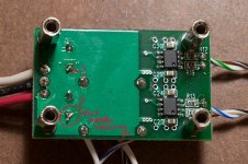
Hey all, so I am building the wire but am having some problems when everything is hooked up. all I hear from my testphones is a constant hum, doesn't change with attenuator.
I have dbl checked the psu and I am getting a good 13V + and -. However once I connect the psu to the se-se board I can't seem to measure any constant voltage.
So i think it might be something with the se-se board. do I need to adjust the psu when connected to the se-se board?
there are no obvious build errors that my eye can see but I've posted pics just in case.
![IMG_20120127_235638[2].jpg](https://www.diyaudio.com/community/data/attachments/243/243836-a7b9e2cfed2f06c71e7dda12f7224558.jpg "IMG_20120127_235638[2].jpg")
![IMG_20120127_235850[1].jpg](https://www.diyaudio.com/community/data/attachments/243/243861-26806deb0dfa3d33b280c3e03226a2a8.jpg "IMG_20120127_235850[1].jpg")
Any idea what it might be?
I have dbl checked the psu and I am getting a good 13V + and -. However once I connect the psu to the se-se board I can't seem to measure any constant voltage.
So i think it might be something with the se-se board. do I need to adjust the psu when connected to the se-se board?
there are no obvious build errors that my eye can see but I've posted pics just in case.
Any idea what it might be?
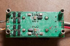
just as just talk alone doesnt help, we need some information and preferably some sign that you have tested the board electrically. without the power supply connected, what do you get when you measure across the power inputs + to G and - to G and signal inputs and outputs L->G and R->G? in general though, the board is a bit messy and there is too much solder.
the main ground in the center of the board looks suspect on both the top and bottom, particularly the top. i havent looked at the layout for the planes, but is the top plane a ground plane, or power plane opc? if its a ground plane, people have to remember that the tabs on the buffers are at full power supply potential i.e. they are live so youve got 2 masive amounts of solder that are causing shorts, if its a power plane then thats ok (although i would clean it up) but the ground wire is definitely shorting.
so before you do anything else, please do the basic tests i posted above; in fact anyone that posts a problem, you should do this test first
hmm yea I seem to have a short somewhere. its very odd measuring across + to G and - to G are both giving me shorts. signal inputs and outputs seem to be shorting as well.
so I seem to be shorting everywhere") , but still unsure as to where it might be occuring. I have removed all wires from the se-se board and am still shorting everywhere.
, but still unsure as to where it might be occuring. I have removed all wires from the se-se board and am still shorting everywhere.
so I seem to be shorting everywhere
, but still unsure as to where it might be occuring. I have removed all wires from the se-se board and am still shorting everywhere.
Last edited:
Sounding Good
Hi guys, two weeks on and listening with the "se-se Wire" is pure bliss.
Pulled a late nighter yesterday and swapped the three JRC5532D op-amps for 3x LME49720MA in my Pioneer DV-757Ai's stereo output stage.
My CDs have never sounded so good... so much detail, so much depth, it's mesmerizing. Apart from a possible headphone upgrade [lcd-2's or he-500's], I'm pretty much content now
Cheers
Paul.
hmm yea I seem to have a short somewhere. its very odd measuring across + to G and - to G are both giving me shorts. signal inputs and outputs seem to be shorting as well.
so I seem to be shorting everywhere
well theres your problem a direct short? like zero or close to zero ohms? or you used continuity test so it triggers only with VERY low ohms? because you will get some connection on each of those except the output, as you will measure the resistance of the decoupling caps to ground and the 10k resistor to ground (not with the signal outputs though, they should be completely open) the signal inputs will each give you 10k and the power supply inputs should give you very high readings in the Mohms, like 3-4Mohms and will change as the cap charges. but if you are getting very low readings or direct shorts on all of these, then you do indeed have some pretty serious issues.
i'll have another look, but given you have problems on all of them, i'm going to call catastrophic soldering failure try to clean up the solder joints with some copper braid and flux, carefully or you will scratch the soldermask
Hi guys, two weeks on and listening with the "se-se Wire" is pure bliss.
Pulled a late nighter yesterday and swapped the three JRC5532D op-amps for 3x LME49720MA in my Pioneer DV-757Ai's stereo output stage.
My CDs have never sounded so good... so much detail, so much depth, it's mesmerizing. Apart from a possible headphone upgrade [lcd-2's or he-500's], I'm pretty much content now
Cheers
Paul.
great Paul, i'm glad you posted a positive experience, it seems we are only getting the problems lately (all of which so far are operator error), as is often the case with a product, you mainly get the people having issues that pipe up while the rest are happily enjoying their gear blissfully unaware. what people have posted in the head-fi thread so far have all good experiences, but given the number of these pcbs out there its all a bit quiet
- Home
- Amplifiers
- Headphone Systems
- "The Wire" Ultra-High Performance Headphone Amplifier - PCB's