I'll either use a solder pad, some 0.1" header pins, or Faston.
My $0.02, FWIW
")
I would cast a vote for the 0.1" header pin. Those headers seem fairly standard for circuit boards and would mate with a lot of different wire types, I believe. Solder pads might have some lift-off problems if they were pulled a bit to hard with a wire attached during assembly. I've pretty much only seen Fastons used in appliances and AC line circuits, but I'm pretty out-of-date too.
Thanks again for all your hard work here, opc!
no, you havent missed it, it hasnt been published yet and there are 3 versions. the bal/se version is about 1A or a touch less, the bal/bal version will probably be about 60-90ma (not pushing them too hard i guess here) for each of the 2 x opa1632 and 4 x 250ma for the buffers. thats a pretty serious salas reg for the resulting 12-15v and 20-22v for ~+/-600ma. so about 12wpc for the buffers and 1-2wpc for the opas.
assuming shunting about 25-30% thats about 40w total for the power supply and some would want to shunt more than that
the above is a guestimate based on supply voltages and known current consumption for the parts and not assuming any losses
assuming shunting about 25-30% thats about 40w total for the power supply and some would want to shunt more than that
the above is a guestimate based on supply voltages and known current consumption for the parts and not assuming any losses
Last edited:
Hi Guys,
I'll take a closer look into what the power requirements are at idle, and at full output. qusp's numbers are a good starting point, but depending on how you feel about power supply design, you might be able to get away with much much less.
Actually delivering 250mA from the buffers is essentially never going to happen unless you're trying to drive a loudspeaker with this amp. On that note, designing a supply that can deliver 1A continuously is probably overkill depending on what you're trying to drive.
I'll hook one up to a power meter and get a better idea of what is needed.
Cheers,
Owen
indeed it was calc for max, i would think someone using salas would be wanting to be able to deliver even higher than the max current. what happens if the power supply cant keep up with the buffers peak delivery? serious question, what sort of clipping behavior?
I was under the impression that the buffers operated in class A? guess i just picked that up as folklore, better go check the datasheet consumption figures; interested in your results though. if not thats actually great news for another project i was looking at with battery power using the buffers in the regs and i ruled them out due to power consumption.
i use very low impedance headphones generally, so i need to cater for a good chunk of that current regardless. i already lowered the number for the opa1632 above to 60-90ma, as they can put out +/-120ma in the power pad version and get pretty hot in the soic8 version. about that opc, dont get too worried its normal for them to get pretty bloody toasty, which is why i like the power pad version
korben69 the buffers if using a separate supply as i'm hoping use up to +/-22v so 44vdc point to point across the rails. you would need minimum 2 supplies for + and -, or a single bipolar supply and i will be running a bipolar supply per channel. so actually i may have understated the max wattage, though current was about right to cover all bases, but even half of that is pretty impractical for a salas reg imo
Last edited:
Salas shunt regs just dump the current that isnt used to ground constantly (thus the name), so they would have to be sized for peak current constantly and have even bigger heatsinks to cope in times of idle. they are a great reg for no compromise lower current cct's, but they just become large, wasteful and impractical for higher currents imo. not a fault of the design, just a product of the type of reg.
Last edited:
OK qusp, I've changed my mind, Salas shunt regs are not designed for this purpose.
Thank's for the explanation
So, opc, I'll take PSU PCB for Bal/Bal version too. Thank you for this add too
Some questions
1° - What are PCB dimensions (Bal/Bal & Bal/Se), BTW is the PSU embedded ?
Goal : looking for a well suited case
2° - I've got an HD-650, about 300 Ohms. Some adjustments required ?
Cheers
Last edited:
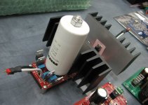
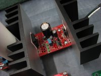
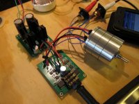
haha cool, yeah can you imagine how crazy it looks? believe me i tried it out with a salas and a sigma22 just for kicks and it looked pretty funny, the pcb was able to perch on top of just one of the caps i was using. the bal/se version of "the wire v1" is ~68 x 53mm
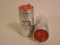
i tried it with 2 of these, which themselves were put together tongue in cheek. my fave is the upside down rifa peh169 cap just crusing there above the pcb connected with 8awg copper foil speaker wire as the screw terminals are too large even for this chunky salas rendition, kinda bobs around. even with 2 x conrad heatsinks it got pretty toasty.
i tried it with 2 of these, which themselves were put together tongue in cheek. my fave is the upside down rifa peh169 cap just crusing there above the pcb connected with 8awg copper foil speaker wire as the screw terminals are too large even for this chunky salas rendition, kinda bobs around. even with 2 x conrad heatsinks it got pretty toasty.
Attachments
Last edited:
no adjustments required at all, read earlier in the thread for my impressions of driving the hd600. it drives them beautifully actually, driven from a balanced source anyway there is easy enough swing to send you deaf
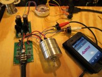
nice cans, its not cased up at the moment, but i'll shoot some pics maybe tomorrow. yes thats the size without psu. i'm running it just with a compact linear tech perfboard reg at the moment.
nice cans, its not cased up at the moment, but i'll shoot some pics maybe tomorrow. yes thats the size without psu. i'm running it just with a compact linear tech perfboard reg at the moment.
Last edited:


haha yep, i was just having a laugh in both building and using it tho. the reg is now destined for my dac, a cmoy is an easy load, some might say apart from the overkill even suitable for a cmoy by comparison.
@KnightOfAwesome: the S22 worked quite well, same story there, dont use the standard small heatsinks if you do and its a crazy size too for this application and its quite unnecessary. it can of course be lessened in size by using the chassis floor as sink
@KnightOfAwesome: the S22 worked quite well, same story there, dont use the standard small heatsinks if you do and its a crazy size too for this application and its quite unnecessary. it can of course be lessened in size by using the chassis floor as sink
Another "Wire" comes to life...
Figured I should finally build this one and get Owen some feedback before the next release. I was hoping to post a finished amp with case work and all, but, I misjudged the completely massive size of the utterly ridiculous attenuator solution I am employing. Yep, the case I bought is not tall enough, DOH!!
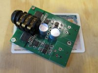
Oh well, instead it remains a work in progress. In any case, she lives! This is my third build with SMD and I forgot how much a PITA it can be working with components this small. I am not kidding, this is the densest SMD build I have attempted yet. I would take a different build tactic next time. It is a bit sloppy, but, acceptable. The amp itself worked first time powered up. I had an issue with an unsoldered side of R15 on the power supply that prevented adjustment of the -15 rail, but, that was a quick fix. From there on, it was smooth sailing.
Since I do not have a balanced source (yet), this one is build single-ended with a gain of 2. This worked out well as I really wanted to try out the Khozmo stepped attenuator. Yes, in this situation, it seems completely overkill (and it is), but why not? Life's short. I really like the Khozmo. The additional steps make a big difference.
The sound is very nice. Extremely sensitive. You will have to pay particular attention to layout and casing to control pickup of noise. I had to move a few things around to get things totally quiet. Even then, any flaws with the source are picked up, so, be warned. Proper layout and casing will go along way with this build.
I have to spend some more time with it, but early impressions are quite positive. The highs are clear and extended, the bass extremely deep and very, very much in control. It steps out of the way and lets the source come through nicely.
BTW, in the last pic, the amp is on top of my State of Florida Drivers License. Yes, it is THAT small!!
Figured I should finally build this one and get Owen some feedback before the next release. I was hoping to post a finished amp with case work and all, but, I misjudged the completely massive size of the utterly ridiculous attenuator solution I am employing. Yep, the case I bought is not tall enough, DOH!!
Oh well, instead it remains a work in progress. In any case, she lives! This is my third build with SMD and I forgot how much a PITA it can be working with components this small.
I am not kidding, this is the densest SMD build I have attempted yet. I would take a different build tactic next time. It is a bit sloppy, but, acceptable. The amp itself worked first time powered up. I had an issue with an unsoldered side of R15 on the power supply that prevented adjustment of the -15 rail, but, that was a quick fix. From there on, it was smooth sailing.Since I do not have a balanced source (yet), this one is build single-ended with a gain of 2. This worked out well as I really wanted to try out the Khozmo stepped attenuator. Yes, in this situation, it seems completely overkill (and it is), but why not? Life's short. I really like the Khozmo. The additional steps make a big difference.
The sound is very nice. Extremely sensitive. You will have to pay particular attention to layout and casing to control pickup of noise. I had to move a few things around to get things totally quiet. Even then, any flaws with the source are picked up, so, be warned. Proper layout and casing will go along way with this build.
I have to spend some more time with it, but early impressions are quite positive. The highs are clear and extended, the bass extremely deep and very, very much in control. It steps out of the way and lets the source come through nicely.
BTW, in the last pic, the amp is on top of my State of Florida Drivers License. Yes, it is THAT small!!
Attachments
- Home
- Amplifiers
- Headphone Systems
- "The Wire" Ultra-High Performance Headphone Amplifier - PCB's