C32,C27,C23,C30 look a little suspect. I cant tell if they are actually soldered or cold solder joints or touching a nearby pad.
I'll reheat the sides and clean up these joints - I don't see ant contact between them and adjacent pads but I agree that there might be some bad joints there.
More hum when touching a part usually means the part is not grounded. The shaft of the volume control is usually grounded through the metal case and there should be no hum when touching it.
Ah I see what I did wrong there - When I took the chassis apart, the knob was no longer grounded to the AC cable's ground through the chassis. When the chassis was closed, I heard no additional effects when touching the knobs, Only when touching the ends of the connected RCA cables, though that is expected.
When you turn the Wire off is there a few seconds of silence before the filter capacitors discharge?
Yes, there is - seems a little unnecessarily audible on the more sensitive gear but yes, I can hesr the caps discharge about a second after I turn the amp off.
Is the output voltage of the Wire buffer chips very close to 0 volts, within a few millivolts. Put your meter on the millivolt AC scale and measure the outputs of the power supply, again should be near 0Volts AC. Also check the AC power supply output voltage with different loads should be the same ie near 0VAC
I'll update on these later tonight (at work right now).
Is the output voltage of the Wire buffer chips very close to 0 volts, within a few millivolts.
Where do I measure this? When I measure between my output headphone Jack's signal and ground leads (each channel individually) my multimeter reads right around 95mV AC and then slowly decreases.
Put your meter on the millivolt AC scale and measure the outputs of the power supply, again should be near 0Volts AC.
Power supply output (again, each of +/- separately) read around 75mV AC and then slowly tapered down.
Also check the AC power supply output voltage with different loads should be the same ie near 0VAC
I don't get this part - shouldn't the AC power supply (I'm assuming from the wall) read 115-117V AC? I think I just might not know what you mean by "AC power supply".
I resoldered all of the caps, they looked pretty bad. Heated all the resistors just to make sure I didn't miss something while I was in there.
There is only one part of the board that confuses me. It looks like the solder bask has been burnt off and the underlying trace has been exposed. I hope this is the case, and not something worse. Can you check if these two points (picture attached of cap removed; the through hole and the pad for C30) should be connected?
Also attached, pics of the resoldered caps.
Capacitor re-solder - Google Drive
All of the above observations were made AFTER resoldering the caps. Touching the volume knob or the front plate still lowers the hum. Touching BOTH the ground of the RCA and the Front plate makes the hum almost completely inaudible (though it's still there just incredibly quiet).
Thanks for your help so far! Any thoughts on where to go from here?
ill get back to you later, out of town guests just came in the door. Yhey should be gone by Monday.
Many thanks - have a good weekend!
More updates from testing:
As stated above, powering from batteries results in almost perfectly quiet operation. Plugging in the Ac power chord (with only the transformer negative lead connected) still causes the same hum. This is leading me to agree with the grounding issue.
I'm doing to simplify the circuit (get rid of the power switch and the potentiometer) and see if that helps. If it doesn't I'm not sure how to move forward. The ground of the RCA is isolated from the chassis, as is the AC ground. I'll update again based on findings on monday night. In the mean time, if you notice anything (as time allows, of course) based on my above reports do let me know.
ill get back to you later, out of town guests just came in the door. Yhey should be gone by Monday.
Hey there, apologies for the bump; any chance you got around to this?
As far as reading voltages. I wanted you to read the AC and DC voltages of the power supply and the output of the buffer chips on the WIRE.
Running from batteries is it completely silent or almost silent? In different posts you say its completely silent and almost silent?
With only 1 wire connected from the power transformer and running from batteries it should be silent. You also mentioned that you thought the hum was 120Hz. If you are getting hum with only one wire connected that should be 60 Hz that you hear.
try moving the transformer and all AC power wiring outside the case.
After 7 years of great listening, The Wire that I built gave up the ghost. I threw the switch and heard loud intermittent static on the output.
I initially thought it was the power supply (failed regs?) since the supply voltage was way down and intermittent. I disconnected the amp board and the PSU recovered to a nice clean +/- 15, so it wasn't that.
I measured the resistance of each rail on the amp board: 3.8Ω V+ to gnd, 6.5Ω V- to gnd. Not good. Maybe one of the buffers?
Since desoldering the buffers was going to be a pain I wanted to be sure of the problem part. I hooked the amp board up to a bench supply and started poking around the board with my finger. All chips were cold but the supply caps were getting hot! I removed the caps and they measured about the same as the rail resistances I mentioned above. I guess they died from the age and being run at 1V below rating?
I powered the amp board without caps, seems like there was no damage. Now I'm just waiting on fresh caps, 25V this time.
Having tried MANY op-amps over the years from all the major manufactures, I've never cared for the "sterile" and "lifeless" sound of many of their op-amps(LM4562, LME49610/20) and buffers(LME49600), but hopefully you will!
The LF356N and BUF-03 were two of National's better sounding offerings unlike any of their "LME" offerings.
Glad to see most of these "sterile" sounding National "LME" offerings being discontinued by T.I..
I used LM4562, LME49610/20 too, but I am not convinced about and use OPA627 in my HA now.
What did you think about the old BUF634 - with or without wide bandwidth mode?
After 7 years of great listening, The Wire that I built gave up the ghost. I threw the switch and heard loud intermittent static on the output.
I initially thought it was the power supply (failed regs?) since the supply voltage was way down and intermittent. I disconnected the amp board and the PSU recovered to a nice clean +/- 15, so it wasn't that.
I measured the resistance of each rail on the amp board: 3.8Ω V+ to gnd, 6.5Ω V- to gnd. Not good. Maybe one of the buffers?
Since desoldering the buffers was going to be a pain I wanted to be sure of the problem part. I hooked the amp board up to a bench supply and started poking around the board with my finger. All chips were cold but the supply caps were getting hot! I removed the caps and they measured about the same as the rail resistances I mentioned above. I guess they died from the age and being run at 1V below rating?
I powered the amp board without caps, seems like there was no damage. Now I'm just waiting on fresh caps, 25V this time.
Hi N Brock,
Good troubleshooting! Glad you found the source of the problem.
That is quite surprising about those caps... polymer caps were kind of in their infancy when I specified them for this project, but I would have expected better than that. Even if you had it plugged in and running 24 hours a day for the past 7 years, that's still only 60,000 hours, and that seems premature for a modern capacitor to be calling it quits.
That failure mode also seems particularly crummy, as it would gradually overload the regulators and cause large amounts of self-heating which I'm sure further hastened the demise of the caps.
Can you comment on heat inside your enclosure? Was it particularly hot in there when the amp was running? In this application, with essentially no ripple current, and what should have been minimal heat, these caps should have lasted essentially forever, even if operated close to their voltage rating.
All that being said, you made the right call on the 25V replacement parts, and hopefully those will last for at least another 10 years.
Happy listening!
Regards,
Owen
Can you comment on heat inside your enclosure? Was it particularly hot in there when the amp was running? In this application, with essentially no ripple current, and what should have been minimal heat, these caps should have lasted essentially forever, even if operated close to their voltage rating.
I never noticed excessive heat. After listening for a few hours I could feel a small amount of warmth coming through the top cover. Actual temps were never measured, maybe they should be this time around. I agree that the caps ought to have lasted longer unless something unintentional was happening.
On the bright side, this has got me thinking about this amp again and I'm tempted to build up one of my rework boards so I can listen to something nice at work.

A quick update for all those following my perils; I found the problem on my amp.
One of the capacitors on the PSU board was only soldered on one side - I noticed becasue I meant to reheat and touchup what looked like a solder joint, but this lead to the capacitor just falling off the board.
I resoldered all the caps on the power board and everything runs perfectly quietly now as long as my signal ground is connected to AC ground. If I leave signal ground floating, I still get a hum but it's much MUCH quieter than before.
Just trying to find a smaller chassis now; I want to make me The Wire build the size of an O2 (convenience), or have it sit inside a shared chassis with my SRM-252s. Should be a cute little build.
Thanks for all your help @opc and @multisync
LOL...
I've also built and listened to Mr. Marsh's HA, but only as preamp since I don't give a big ole' damn about headphones.
I have to admit it sounds a little better than this so called "Wire" nonsense, but still sucks moose balls compared to the Schiit Magni 3.
Sorry guys... but sometimes DIY just can NOT compete with affordable commercial designs like the Magni 3.

The "Schiit" amplifier lives up to its unfortunate name.
The DC spikes from them at switch on and off are dreadful, and the harmonic distortion and slew-rate distortion are appalling. It wasn't "designed", it was thrown together by someone with little real understanding of electronics.
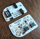
Something I've been working on, NanoWire
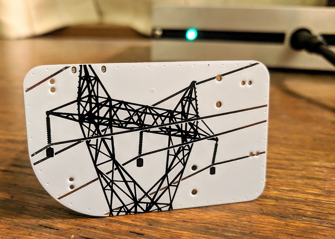
More information to follow.
Ooooh prettyyyy!
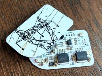
Okay, I populated one of my NanoWire boards and immediately found some errors. The linear regulators I used are not compatible with my DC-DC selection. At the moment I have it working with the regulators removed. There is also a lot of noise when power and audio are both supplied from the same device, probably a ground loop. I hope to fix this when I re-do the power supply section.
If there is interest I hope to offer these boards in a group buy or similar once all the issues are ironed out. Suggestions and comments are welcomed and I will consider them when making design revisions. Below I have copied a draft of my blog post that explains the thought process for this project.
Design Goals:
Single ended circuit
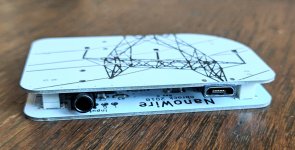
Shrink total size - As built: 65 x 40 x 8mm
Integrate power supply
Enclosure solution - hobbyists don't need to drill holes
The original circuit used LME49990 op amps which are now obsolete. I opted to sub in OPA1612, because of its comparably high performance. The dual package offers some layout benefits and a slightly reduced cost over using two OPA1611. TI claims "The dual version features completely independent circuitry for lowest crosstalk and freedom from interactions between channels, even when overdriven or overloaded." so hopefully there aren't too many complaints from the purists.
This design is USB powered. There's a DC-DC converter that will supply +/- 9V. Linear regulators make the final supply +/- 8V. Power output is limited by the supply. The converter I chose is 2 watts and there is approximately 100 mA drive current available. Theoretically the amp will deliver up to 80 mW / ch into 32 ohms, 282 mW /ch into 113 ohms, and 53 mW / ch into 600 ohms. Below 113 ohms it's current limited, above 113 ohms it's voltage limited.
I do not have the equipment or experience to characterize this new variant the way opc did. Because some parts are different, the layout has changed, it's a two layer board, and I'm not an audio designer / electrical engineer, I have to assume that the measured performance will be worse. If anyone has the ability and desire to make measurements I'll send you some boards once they are working properly.
I had a discussion with another enthusiast at the 2018 Burning Amp festival about cases. In his experience the enclosure typically took more than half of a project's resources (money, time, mental effort). He often resorted to modifying "found" enclosures that were larger and uglier than he'd have liked.
I wanted to include an enclosure solution for the less mechanically inclined. I explored what it would take to supply an appropriately sized, inexpensive, attractive case with all the right holes in the right places. Aliexpress has a wide selection of cases available. Most of what I looked at were aluminum extrusions with a front and back plate. Nearly every listing offers customization of the case for an additional fee. The typical offering is custom extrusion length, color/finish, cut or punched holes, and silkscreen graphics.
As my layout continued to shrink I briefly considered a fully machined enclosure as well. I've used mfg.com in the past for job shop type work with good results and would feel comfortable using them again for a small amp case.
A few things put me off having custom cases made. Unknown demand was a major factor. The original boards made by opc haven't been available for over 5 years and as a result there isn't much recent discussion on the build thread. People may no longer be interested in the design and I might not have the quantity needed to make a custom order of cases worthwhile. On the other hand, there may be a back log of people waiting to build and the quantity could become more than I am prepared to handle. This leads into my next concern, capital. Ordering anything in large quantity requires a chunk of money to be set aside. Aliexpress offers reasonable prices but my experience with their sellers has been mixed which does not inspire confidence. Since this is a hobby for me and not a business it's hard to justify the risk, at least for a first run.
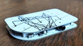
Kicking ideas around and fiddling with the layout eventually led me to a design that uses two PCBs stacked together with all components sandwiched between them. The main lower board has the audio circuitry and linear regulators on it and a number of different ways to connect to it. The upper board is an interface board. It's the same shape as the main board and sits directly over it, connected by a few headers. It has the 3.5mm input + output connectors, USB connector, and DC-DC PSU module. The outer most copper layers of the assembly are ground plane only. This should prevent any shorts if the amp rests on anything conductive. To make manual assembly a bit easier, all the parts that need mechanical alignment have board guides. The interface board is optional. Some builders will want to use their own connectors or power supply by wiring directly to the through holes provided on the main board. I plan to make at least one more interface board variant with a beefier power supply, RCA input, and 1/4" jack output. I think an integrated DAC board would be pretty slick, but that's a little outside my current abilities.
If there is interest I hope to offer these boards in a group buy or similar once all the issues are ironed out. Suggestions and comments are welcomed and I will consider them when making design revisions. Below I have copied a draft of my blog post that explains the thought process for this project.
Design Goals:
Single ended circuit
Shrink total size - As built: 65 x 40 x 8mm
Integrate power supply
Enclosure solution - hobbyists don't need to drill holes
The original circuit used LME49990 op amps which are now obsolete. I opted to sub in OPA1612, because of its comparably high performance. The dual package offers some layout benefits and a slightly reduced cost over using two OPA1611. TI claims "The dual version features completely independent circuitry for lowest crosstalk and freedom from interactions between channels, even when overdriven or overloaded." so hopefully there aren't too many complaints from the purists.
This design is USB powered. There's a DC-DC converter that will supply +/- 9V. Linear regulators make the final supply +/- 8V. Power output is limited by the supply. The converter I chose is 2 watts and there is approximately 100 mA drive current available. Theoretically the amp will deliver up to 80 mW / ch into 32 ohms, 282 mW /ch into 113 ohms, and 53 mW / ch into 600 ohms. Below 113 ohms it's current limited, above 113 ohms it's voltage limited.
I do not have the equipment or experience to characterize this new variant the way opc did. Because some parts are different, the layout has changed, it's a two layer board, and I'm not an audio designer / electrical engineer, I have to assume that the measured performance will be worse. If anyone has the ability and desire to make measurements I'll send you some boards once they are working properly.
I had a discussion with another enthusiast at the 2018 Burning Amp festival about cases. In his experience the enclosure typically took more than half of a project's resources (money, time, mental effort). He often resorted to modifying "found" enclosures that were larger and uglier than he'd have liked.
I wanted to include an enclosure solution for the less mechanically inclined. I explored what it would take to supply an appropriately sized, inexpensive, attractive case with all the right holes in the right places. Aliexpress has a wide selection of cases available. Most of what I looked at were aluminum extrusions with a front and back plate. Nearly every listing offers customization of the case for an additional fee. The typical offering is custom extrusion length, color/finish, cut or punched holes, and silkscreen graphics.
As my layout continued to shrink I briefly considered a fully machined enclosure as well. I've used mfg.com in the past for job shop type work with good results and would feel comfortable using them again for a small amp case.
A few things put me off having custom cases made. Unknown demand was a major factor. The original boards made by opc haven't been available for over 5 years and as a result there isn't much recent discussion on the build thread. People may no longer be interested in the design and I might not have the quantity needed to make a custom order of cases worthwhile. On the other hand, there may be a back log of people waiting to build and the quantity could become more than I am prepared to handle. This leads into my next concern, capital. Ordering anything in large quantity requires a chunk of money to be set aside. Aliexpress offers reasonable prices but my experience with their sellers has been mixed which does not inspire confidence. Since this is a hobby for me and not a business it's hard to justify the risk, at least for a first run.
Kicking ideas around and fiddling with the layout eventually led me to a design that uses two PCBs stacked together with all components sandwiched between them. The main lower board has the audio circuitry and linear regulators on it and a number of different ways to connect to it. The upper board is an interface board. It's the same shape as the main board and sits directly over it, connected by a few headers. It has the 3.5mm input + output connectors, USB connector, and DC-DC PSU module. The outer most copper layers of the assembly are ground plane only. This should prevent any shorts if the amp rests on anything conductive. To make manual assembly a bit easier, all the parts that need mechanical alignment have board guides. The interface board is optional. Some builders will want to use their own connectors or power supply by wiring directly to the through holes provided on the main board. I plan to make at least one more interface board variant with a beefier power supply, RCA input, and 1/4" jack output. I think an integrated DAC board would be pretty slick, but that's a little outside my current abilities.
Attachments
Last edited:
- Home
- Amplifiers
- Headphone Systems
- "The Wire" Ultra-High Performance Headphone Amplifier - PCB's