yes... problem.
Sneak a piece of tape in there, or move the heatsink. The can of the caps will be at the same potential as the -pin of the cap and the heatsink will be at V- potential. Depending on which cap it's touching, this could be an issue.
Better safe than sorry.
The rest looks good, but I would straighten up those input resistors!
Cheers,
Owen
I removed them as I believe in as less metallic material in the vicinity of signal as possible. I leave also the crocked oriented resistors as I don't want to put anymore thermal stress on the components. I judge them to have adequate connectivity. They won't be visible anyway.
TNT:
ghellman:
It's really tough to troubleshoot this particular issue from abroad, but I would follow what Neeviour said and start doing a passive resistance measurement of every part possible with the unit powered down. The key here is to measure the resistance of a soldered resistor by putting the meter on two adjacent pads that are electrically connected. As an example, if you want to make sure R13 is correctly soldered (and the correct value) then you would measure with your meter from the input pad (H20) through to the non-GND pad on R14, or to pin 3 of the op-amp. If you measure 1k resistance there, then you can be pretty sure that R13 is correctly soldered and the correct value.
The key is not to measure across the actual resistor pads as this doesn't tell you if you have a cold solder joint. Measuring across adjacent pads will tell you if the part is electrically connected to the pads on the PCB.
If the channel is not working at all (eg. dead silence), then it's either R13, R16, U9 or U10. All the other parts would either not cause an issue, or would cause high levels of DC on the output. Measure the output for DC first (meter set to DC setting, and measure from headphone output to GND) and if you see anything higher than a few mV then there is definitely a problem.
If you don't have DC at the output, and still don't see a signal, it pretty much has to be R13, U9 or U10.
Since the SE-SE shares a common power supply, and one channel works, you can almost be certain that the other channel is getting proper power, so there is little benefit to measuring the DC levels at the op-amp power pins. This only really risks you shorting something out while measuring.
Give the above a try, and let us know what your results are.
Regards,
Owen
Using what you and Neeviour said - with power off, just measuring resistance, I found that I COULD NOT get my R19 to attach electrically to the pad - so it did not register a resistance from H36 to pin#2 of op amp U11. I eventually tried a different resistor and got that to attach. I guess my trying to line it up properly eventually burned off some of the "connector".
One problem down, but still more to find.
That is a great test - because R19 certainly looked attached - it just did not conduct....
I also do find some DC at the headphone output (even on the side that works.) - one is 1.2VDC the other about 1.6VDC
so there are still problems... (C27 and C32? or other capacitors?)
Thanks again for help (and future help)
After little "this and that" ") it plays nicely on my Philips HP-890. First package from DigiKey to make the PSU which also will require a parcel from Mouser. It was one solder that was that when i pressure was applied by the pin of the Ohm meter, created connectivity but when the pin was release, no connection where there. Tricky to find but I git suspicious when applying a signal in and nothing out (this was with no power fed to the amp).
it plays nicely on my Philips HP-890. First package from DigiKey to make the PSU which also will require a parcel from Mouser. It was one solder that was that when i pressure was applied by the pin of the Ohm meter, created connectivity but when the pin was release, no connection where there. Tricky to find but I git suspicious when applying a signal in and nothing out (this was with no power fed to the amp).
All good except I can't really find my anticipated 6dB gain, I use 15 k as Rin and 33k as Rfb.
//
it plays nicely on my Philips HP-890. First package from DigiKey to make the PSU which also will require a parcel from Mouser. It was one solder that was that when i pressure was applied by the pin of the Ohm meter, created connectivity but when the pin was release, no connection where there. Tricky to find but I git suspicious when applying a signal in and nothing out (this was with no power fed to the amp).All good except I can't really find my anticipated 6dB gain, I use 15 k as Rin and 33k as Rfb.
//
It was one solder that was that when i pressure was applied by the pin of the Ohm meter, created connectivity but when the pin was release, no connection where there.
This is why you need to measure from pads to pads for expected resistance instead of from the pin to the pad. I've had this problem before too.
This, from my understanding, is a cold joint.To clarify - the pressure was made on top of a resistor, pushing it down onto the pad.
The procedure of soldering, is that BOTH surfaces are heated up, and the flowing solder fill the gap. Then during solidification, the solder interacts with the item surfaces and forms alloying bond with the surfaces, which provides both electrical and mechanical connection. If a surface is not heated up enough, it might failed to create a bond. You may still get physical contact (and may work well for long enough), but not "bonding".
A question here.
For the PSU V2, I see the component configures are basically from the reference design in TI's datasheet here.
The Cff is a C0G/NP0 ceramic cap, 0.01uF and Cnr is a X7R ceramic cap 1uF. The manual did not specify if it should be just this value, or anything equal or larger than these? Especially the Cff using a C0G/NP0 gets me wonder if it is a "Audiophile style" or a necesity? Purely out of curiosity here.
neeviour, see Samuel Groner's page discussing differences in ceramic capacitor dielectrics. It's an engineering choice, none of the decisions in Owen's designs are for 'audiophile' reasons but the designs are not an exercise in cost minimisation so some choices my not be 'audible' but there will be better measured performance.
neeviour, see Samuel Groner's page discussing differences in ceramic capacitor dielectrics. It's an engineering choice, none of the decisions in Owen's designs are for 'audiophile' reasons but the designs are not an exercise in cost minimisation so some choices my not be 'audible' but there will be better measured performance.
Good to know that, I am very adapted to "engineer style".
I am trying to get educated for the cap choices here, in capacitance and type. As a background I understand what C0G/NP0 is. Is it that the capacitance need to be very stable here? What if a larger/smaller caps used (mostly for Cff here)? I am no EE, but interested and would like to learn.
Last edited:
BAL-BAL!
Too late
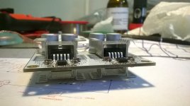
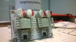
The hetsink has contact with the caps - problem?
yes... problem.
Sneak a piece of tape in there, or move the heatsink. The can of the caps will be at the same potential as the -pin of the cap and the heatsink will be at V- potential. Depending on which cap it's touching, this could be an issue.
Better safe than sorry.
It seems that the os-con and pans FP polymer caps cans are not conductive. I mean it looks like bare metal can but may have some coating on them. So I guess touching them would not be an issue, but may not apply to other aluminum caps.
The Cff is a C0G/NP0 ceramic cap, 0.01uF and Cnr is a X7R ceramic cap 1uF. The manual did not specify if it should be just this value, or anything equal or larger than these? Especially the Cff using a C0G/NP0 gets me wonder if it is a "Audiophile style" or a necesity? Purely out of curiosity here.
Page 12 of the voltage regulator datasheet under "capacitor recomdendations" says the noise reduction and feedforward caps need to be low ESR and recommends (at least) X7R or X5R MLCCs. 1uF MLCCs are not available in COG, so X7R is the best you can do there. At 0.01uF the X7R and COG cost the same these days, about $0.35 USD each for 5% tolerance 50V at Mouser (leaded), so might was well go with COG which won't have termperature and voltage variances to worry about.
Also on page 12 TI recommends the 1uF for noise reduction cap and the 0.01uF for feedforward and makes the statement "the solution shown delivers minimum noise levels... and PSRR levels..." I always go under the assumption that data sheet recommendations are the best possible for any given chip, given the enormous resources the chip companies have to devote to testing, some really smart people on board, and a financial stake in getting the recommends right to sell more chips.
Last edited:
Page 12 of the voltage regulator datasheet under "capacitor recomdendations" says the noise reduction and feedforward caps need to be low ESR and recommends (at least) X7R or X5R MLCCs. 1uF MLCCs are not available in COG, so X7R is the best you can do there. At 0.01uF the X7R and COG cost the same these days, about $0.35 USD each for 5% tolerance 50V at Mouser (leaded), so might was well go with COG which won't have termperature and voltage variances to worry about.
Also on page 12 TI recommends the 1uF for noise reduction cap and the 0.01uF for feedforward and makes the statement "the solution shown delivers minimum noise levels... and PSRR levels..." I always go under the assumption that data sheet recommendations are the best possible for any given chip, given the enormous resources the chip companies have to devote to testing, some really smart people on board, and a financial stake in getting the recommends right to sell more chips.
Sounds reasonable to me. The manual did not specify C0G though, but as you said, minimal cost difference for most.
I just set most things up. PSU V2, positive rail to GND 15.18V, negative rail to GND -15.09. Output offset: input short, 0.2mV and 0mV; input open, 1.5mV and -2.2mV. Looks alright?
Now a long waiting for the chassis and front panel work. Will post the results.
A (general) question here, what kind of effect does the non-equal bipolar voltage have? To what extend we should concern about it, say, for the Wire?
- Home
- Amplifiers
- Headphone Systems
- "The Wire" Ultra-High Performance Headphone Amplifier - PCB's