[h=Kit Contents]%2[/h]
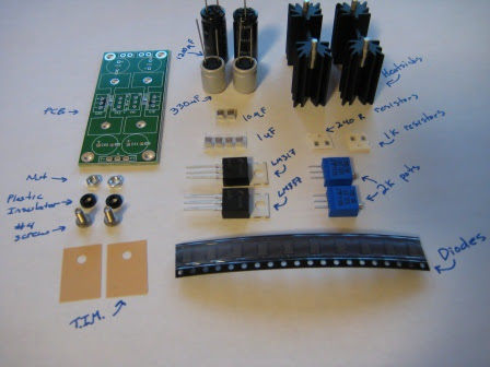
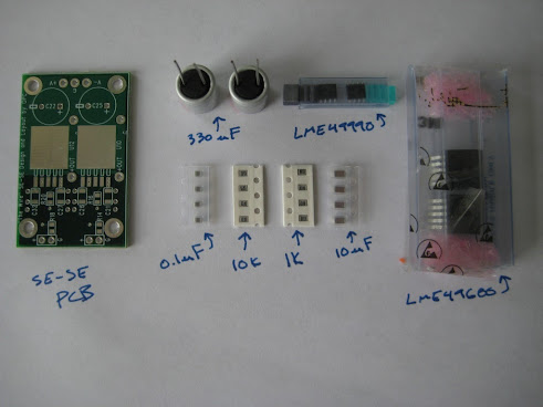
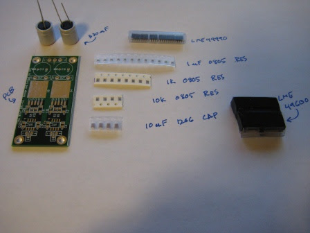
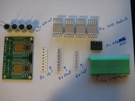
Each kit should contain all of the parts specified in the BOM for that kit. The photos below show each of the kits as they are packaged. The first step should be to open each kit and spread the contents onto a white sheet of paper to ensure all parts are present. Some parts are very light, and small, and can stick easily inside the bag they came in, so be sure to check the bag thoroughly before discarding it.
Compare your kit contents to the photos and the BOM for each respective kit and identify each part. There are no spares or optional parts with these kits, so you will be installing every part included with the kits on the PCB.
None of the parts should be ambiguous in any way, even once they are removed from their packaging. The only exception to this is the 1uF and 10uF 1210 capacitors for the PSU. These parts should be kept in their respective packaging until it is time to solder them in order to avoid confusing the parts. The only way they can be identified is by the number of each part included with the kits (2 x 10uF and 4 x 1 uF). You could also identify the parts with a multi-meter that can measure capacitance.
All resistors are clearly marked on the top with the value. If your eyesight is good, you should be able to see these markings without any issues. If you have poor eyesight, a magnifying glass may be required.
PSU
SE-SE
BAL-SE
BAL_BAL
[h=Assembly Instructions]%2[/h]
Once all parts have been identified, it’s time to start soldering all parts one at a time. It is always best to start with the smallest and most difficult parts in a given area, so avoid the temptation to solder the larger parts just to get them done. The order of assembly is critical, especially with the PSU.
PSU
1. Solder all ten of the SMA diodes to the underside of the PCB. These are easy parts to solder and should let you get a feel for SMD work if you’ve never done it before.
2. Solder the four 0805 resistors in place, making sure not to confuse the two values. Two are on the top of the board, and two are on the bottom.
3. Solder the four 1uF 1210 capacitors in place making sure to get the locations correct!
4. Solder the two 10uF 1210 capacitors in place making sure to get the locations correct!
5. At this point, all the SMD parts should be done.
6. At this point I always take the time to clean the entire board thoroughly with 99% rubbing alcohol and an old toothbrush to remove the flux. After a few applications of alcohol and lots of scrubbing, all the flux should be gone and the boards can be rinsed with soap and water to eliminate any remaining residue. Dry the boards well, and if available, use compressed air to get any water out from cracks or component holes in the PCB. This step is optional.
7. Solder the two 2k pots in place.
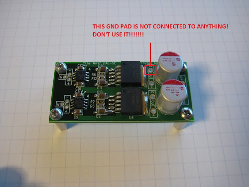
8. Attach the LM regulators to the heatsinks using the supplied thermal interface material and the plastic insulating washers with the supplied #4 hardware. Ensure that the parts are tightly secured, well centered, and electrically isolated from the heatsink.
9. Install the assembly from step 8 into the board and solder both the regulator and the heatsink pins. It take a great deal of heat to solder the pins for the heatsinks to the ground plane!
10. Solder the four PTH caps in place making sure they are installed with the correct polarity and held tightly in the correct upright position. It is best if these caps do not lean against the heatsinks. The solid polymer caps are sensitive to overheating, so be gentle with them while soldering.
11. At this point I like to locally clean the flux off the PTH joints using rubbing alcohol and a paper towel. It’s best not to immerse the completed board in water since the pots, caps and thermal interface material will not like getting wet.
12. You’re done! Turn each pot fully clockwise (yes they are backwards) to get minimum output voltage, then power it up and adjust to the desired voltage. Do not ever, under any circumstances, exceed 16V output or you will ruin the polymer filter caps.
SE-SE
1. Solder the two LME49900 ICs in place.
2. Solder all four of the 1uF 0805 bypass caps in place
3. Solder the two LME49600 ICs in place. Start with the pins and then solder the tab.
4. Solder all four of the 10uF 1206 bypass caps in place.
5. Solder all eight of the 0805 resistors in place
6. At this point I always take the time to clean the entire board thoroughly with 99% rubbing alcohol and an old toothbrush to remove the flux. After a few applications of alcohol and lots of scrubbing, all the flux should be gone and the boards can be rinsed with soap and water to eliminate any remaining residue. Dry the boards well, and if available, use compressed air to get any water out from cracks or component holes in the PCB. This step is optional.
7. Solder the two PTH polymer caps in place being careful not to overheat the pins.
8. Locally clean the flux off of the capacitor joints using a paper towel and rubbing alcohol.
9. You’re done! Hook up the inputs and outputs, and power it up.
BAL-SE
1. Solder the six LME49900 ICs in place.
2. Solder all twelve of the 1uF 0805 bypass caps in place
3. Solder the two LME49600 ICs in place. Start with the pins and then solder the tab.
4. Solder all four of the 10uF 1206 bypass caps in place.
5. Solder all twelve of the 0805 resistors in place
6. At this point I always take the time to clean the entire board thoroughly with 99% rubbing alcohol and an old toothbrush to remove the flux. After a few applications of alcohol and lots of scrubbing, all the flux should be gone and the boards can be rinsed with soap and water to eliminate any remaining residue. Dry the boards well, and if available, use compressed air to get any water out from cracks or component holes in the PCB. This step is optional.
7. Solder the two PTH polymer caps in place being careful not to overheat the pins.
8. Locally clean the flux off of the capacitor joints using a paper towel and rubbing alcohol.
9. You’re done! Hook up the inputs and outputs, and power it up.
A SPECIAL NOTE ABOUT THE BAL-SE BOARD:
BAL-BAL
1. Solder the two OPA1632 ICs in place
2. Solder the six 0805 1uF bypass caps in place
3. Solder the eight 0805 resistors in place
4. Solder the four LME49600 ICs in place. Start with the pins and then solder the tab.
5. Solder all eight of the 10uF 1206 bypass caps in place.
6. At this point I always take the time to clean the entire board thoroughly with 99% rubbing alcohol and an old toothbrush to remove the flux. After a few applications of alcohol and lots of scrubbing, all the flux should be gone and the boards can be rinsed with soap and water to eliminate any remaining residue. Dry the boards well, and if available, use compressed air to get any water out from cracks or component holes in the PCB. This step is optional.
7. Carefully solder on the SMD heatsinks for each LME49600. These parts are relatively difficult to solder, and required a lot of heat and careful positioning. After installing these, clean the board again as in step 6.
8. Solder the four PTH polymer caps in place being careful not to overheat the pins.
9. Locally clean the flux off of the capacitor joints using a paper towel and rubbing alcohol.
10. You’re done! Hook up the inputs and outputs, and power it up.
[h=Setup and Use]%2[/h]
Once everything is built, it’s best to test and set the PSU before making any connections between boards. For typical use, it’s best to set the PSU at +/- 12VDC. If you need more headroom then the supply can be set as high as +/-15.5VDC.
Once the power supply is tested and working, connect it to the amplifier board. Use the largest wire possible between the two boards. Using 18AWG wire is ideal. Try to keep these wires as short as possible while still maintaining good chassis layout and keeping the amp board away from the power transformer.
Outputs should be wired to the output jack of choice. The ground connection should be kept as short as possible between the jack and the amplifier output. A long lead with lots of resistance will cause higher crosstalk between channels.
The inputs should be carefully wired in, and tightly twisted together to improve noise rejection.
Never power the amplifier up for the first time with your headphones connected! If there is a problem, you could cause serious damage to your headphones. Always test the output for DC offset before connecting headphones for the first time. Once the amplifier has been proven to work correctly, you do not need to take these precautions.
Be very cautious that your various sources do not have DC at their outputs. The Wire is a DC coupled amplifier and as such will pass or amplify (depending on the gain selected) any DC that appears at its input. If you’re connecting an unknown source, always test the output for DC before connecting your headphones!
If you have access to a program like RMAA or any other measurement equipment, it’s always a great idea to run a quick test to ensure everything is working as you expect.
Please enjoy your kit, and feel free to contact me with any questions or issues.
[h=Rework Boards]%2[/h]
Several people were given the option of buying the first run of SE-SE boards that had a mistake where the power supplies to the two front end op-amps were reversed. Anyone who ordered an SE-SE kit need not worry about this as their kits came with proper boards that were fixed.
For those who ordered rework boards, the instructions are as follows:
1. Cut each trace on the red lines using a utility knife.
2. Peel the entire trace off the board between the two cut points.
3. Solder in some pre-formed solid copper wire (22-24AWG) along the black lines. Tack one end to the capacitor pad, and the other two the appropriate vias or via.
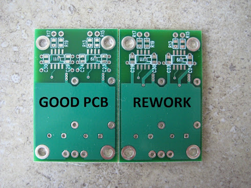
If you have both types of boards, you can use the image below to help distinguish them. Be sure not to confuse the two boards!
Each kit should contain all of the parts specified in the BOM for that kit. The photos below show each of the kits as they are packaged. The first step should be to open each kit and spread the contents onto a white sheet of paper to ensure all parts are present. Some parts are very light, and small, and can stick easily inside the bag they came in, so be sure to check the bag thoroughly before discarding it.
Compare your kit contents to the photos and the BOM for each respective kit and identify each part. There are no spares or optional parts with these kits, so you will be installing every part included with the kits on the PCB.
None of the parts should be ambiguous in any way, even once they are removed from their packaging. The only exception to this is the 1uF and 10uF 1210 capacitors for the PSU. These parts should be kept in their respective packaging until it is time to solder them in order to avoid confusing the parts. The only way they can be identified is by the number of each part included with the kits (2 x 10uF and 4 x 1 uF). You could also identify the parts with a multi-meter that can measure capacitance.
All resistors are clearly marked on the top with the value. If your eyesight is good, you should be able to see these markings without any issues. If you have poor eyesight, a magnifying glass may be required.
PSU
SE-SE
BAL-SE
BAL_BAL
[h=Assembly Instructions]%2[/h]
Once all parts have been identified, it’s time to start soldering all parts one at a time. It is always best to start with the smallest and most difficult parts in a given area, so avoid the temptation to solder the larger parts just to get them done. The order of assembly is critical, especially with the PSU.
PSU
1. Solder all ten of the SMA diodes to the underside of the PCB. These are easy parts to solder and should let you get a feel for SMD work if you’ve never done it before.
2. Solder the four 0805 resistors in place, making sure not to confuse the two values. Two are on the top of the board, and two are on the bottom.
3. Solder the four 1uF 1210 capacitors in place making sure to get the locations correct!
4. Solder the two 10uF 1210 capacitors in place making sure to get the locations correct!
5. At this point, all the SMD parts should be done.
6. At this point I always take the time to clean the entire board thoroughly with 99% rubbing alcohol and an old toothbrush to remove the flux. After a few applications of alcohol and lots of scrubbing, all the flux should be gone and the boards can be rinsed with soap and water to eliminate any remaining residue. Dry the boards well, and if available, use compressed air to get any water out from cracks or component holes in the PCB. This step is optional.
7. Solder the two 2k pots in place.
8. Attach the LM regulators to the heatsinks using the supplied thermal interface material and the plastic insulating washers with the supplied #4 hardware. Ensure that the parts are tightly secured, well centered, and electrically isolated from the heatsink.
9. Install the assembly from step 8 into the board and solder both the regulator and the heatsink pins. It take a great deal of heat to solder the pins for the heatsinks to the ground plane!
10. Solder the four PTH caps in place making sure they are installed with the correct polarity and held tightly in the correct upright position. It is best if these caps do not lean against the heatsinks. The solid polymer caps are sensitive to overheating, so be gentle with them while soldering.
11. At this point I like to locally clean the flux off the PTH joints using rubbing alcohol and a paper towel. It’s best not to immerse the completed board in water since the pots, caps and thermal interface material will not like getting wet.
12. You’re done! Turn each pot fully clockwise (yes they are backwards) to get minimum output voltage, then power it up and adjust to the desired voltage. Do not ever, under any circumstances, exceed 16V output or you will ruin the polymer filter caps.
SE-SE
1. Solder the two LME49900 ICs in place.
2. Solder all four of the 1uF 0805 bypass caps in place
3. Solder the two LME49600 ICs in place. Start with the pins and then solder the tab.
4. Solder all four of the 10uF 1206 bypass caps in place.
5. Solder all eight of the 0805 resistors in place
6. At this point I always take the time to clean the entire board thoroughly with 99% rubbing alcohol and an old toothbrush to remove the flux. After a few applications of alcohol and lots of scrubbing, all the flux should be gone and the boards can be rinsed with soap and water to eliminate any remaining residue. Dry the boards well, and if available, use compressed air to get any water out from cracks or component holes in the PCB. This step is optional.
7. Solder the two PTH polymer caps in place being careful not to overheat the pins.
8. Locally clean the flux off of the capacitor joints using a paper towel and rubbing alcohol.
9. You’re done! Hook up the inputs and outputs, and power it up.
BAL-SE
1. Solder the six LME49900 ICs in place.
2. Solder all twelve of the 1uF 0805 bypass caps in place
3. Solder the two LME49600 ICs in place. Start with the pins and then solder the tab.
4. Solder all four of the 10uF 1206 bypass caps in place.
5. Solder all twelve of the 0805 resistors in place
6. At this point I always take the time to clean the entire board thoroughly with 99% rubbing alcohol and an old toothbrush to remove the flux. After a few applications of alcohol and lots of scrubbing, all the flux should be gone and the boards can be rinsed with soap and water to eliminate any remaining residue. Dry the boards well, and if available, use compressed air to get any water out from cracks or component holes in the PCB. This step is optional.
7. Solder the two PTH polymer caps in place being careful not to overheat the pins.
8. Locally clean the flux off of the capacitor joints using a paper towel and rubbing alcohol.
9. You’re done! Hook up the inputs and outputs, and power it up.
A SPECIAL NOTE ABOUT THE BAL-SE BOARD:
BAL-BAL
1. Solder the two OPA1632 ICs in place
2. Solder the six 0805 1uF bypass caps in place
3. Solder the eight 0805 resistors in place
4. Solder the four LME49600 ICs in place. Start with the pins and then solder the tab.
5. Solder all eight of the 10uF 1206 bypass caps in place.
6. At this point I always take the time to clean the entire board thoroughly with 99% rubbing alcohol and an old toothbrush to remove the flux. After a few applications of alcohol and lots of scrubbing, all the flux should be gone and the boards can be rinsed with soap and water to eliminate any remaining residue. Dry the boards well, and if available, use compressed air to get any water out from cracks or component holes in the PCB. This step is optional.
7. Carefully solder on the SMD heatsinks for each LME49600. These parts are relatively difficult to solder, and required a lot of heat and careful positioning. After installing these, clean the board again as in step 6.
8. Solder the four PTH polymer caps in place being careful not to overheat the pins.
9. Locally clean the flux off of the capacitor joints using a paper towel and rubbing alcohol.
10. You’re done! Hook up the inputs and outputs, and power it up.
[h=Setup and Use]%2[/h]
Once everything is built, it’s best to test and set the PSU before making any connections between boards. For typical use, it’s best to set the PSU at +/- 12VDC. If you need more headroom then the supply can be set as high as +/-15.5VDC.
Once the power supply is tested and working, connect it to the amplifier board. Use the largest wire possible between the two boards. Using 18AWG wire is ideal. Try to keep these wires as short as possible while still maintaining good chassis layout and keeping the amp board away from the power transformer.
Outputs should be wired to the output jack of choice. The ground connection should be kept as short as possible between the jack and the amplifier output. A long lead with lots of resistance will cause higher crosstalk between channels.
The inputs should be carefully wired in, and tightly twisted together to improve noise rejection.
Never power the amplifier up for the first time with your headphones connected! If there is a problem, you could cause serious damage to your headphones. Always test the output for DC offset before connecting headphones for the first time. Once the amplifier has been proven to work correctly, you do not need to take these precautions.
Be very cautious that your various sources do not have DC at their outputs. The Wire is a DC coupled amplifier and as such will pass or amplify (depending on the gain selected) any DC that appears at its input. If you’re connecting an unknown source, always test the output for DC before connecting your headphones!
If you have access to a program like RMAA or any other measurement equipment, it’s always a great idea to run a quick test to ensure everything is working as you expect.
Please enjoy your kit, and feel free to contact me with any questions or issues.
[h=Rework Boards]%2[/h]
Several people were given the option of buying the first run of SE-SE boards that had a mistake where the power supplies to the two front end op-amps were reversed. Anyone who ordered an SE-SE kit need not worry about this as their kits came with proper boards that were fixed.
For those who ordered rework boards, the instructions are as follows:
1. Cut each trace on the red lines using a utility knife.
2. Peel the entire trace off the board between the two cut points.
3. Solder in some pre-formed solid copper wire (22-24AWG) along the black lines. Tack one end to the capacitor pad, and the other two the appropriate vias or via.
If you have both types of boards, you can use the image below to help distinguish them. Be sure not to confuse the two boards!
Attachments
")
+1 MarcWhere is the link to price/purchase? Thanks.
Most recent info here - http://www.diyaudio.com/forums/vend...jects-available-here-bal-bal-se-se-lpuhp.html
Yup!
BOM for PSU V2 can be found here:
https://docs.google.com/spreadsheet/ccc?key=0AnMLwB9mdXl2dDN6V05FanpQN1BFR2xRcENORVFSNXc&usp=sharing
Schematic for PSU V2 can be found here:
https://drive.google.com/file/d/0B3MLwB9mdXl2Z3N4WWh4MU93SW8/edit?usp=sharing
Regards,
Owen
BOM for PSU V2 can be found here:
https://docs.google.com/spreadsheet/ccc?key=0AnMLwB9mdXl2dDN6V05FanpQN1BFR2xRcENORVFSNXc&usp=sharing
Schematic for PSU V2 can be found here:
https://drive.google.com/file/d/0B3MLwB9mdXl2Z3N4WWh4MU93SW8/edit?usp=sharing
Regards,
Owen
BOM for PSU V2 can be found here:
https://docs.google.com/spreadsheet/...Xc&usp=sharing
Schematic for PSU V2 can be found here:
https://drive.google.com/file/d/0B3M...it?usp=sharing
Please put the PSU V2 links on the front page. I was searching forever for this info and was getting really confused with the original PSU info still floating around. Im sure there will be a lot of changes to this page once the new NTD1's are released.
Last edited:
- Status
- This old topic is closed. If you want to reopen this topic, contact a moderator using the "Report Post" button.
- Home
- diyaudio.com Wiki
- "The Wire" Headphone Amp Build Wiki