There is a Wiki here which contains all the project information, documentation and details for all "The Wire" projects:
http://www.diyaudio.com/forums/showwiki.php?title=The_Wire_-_All_Boards_and_Kits_Explained_Here
Hi Guys,
It has been a while since I’ve posted a completely new project, but I have been working away on a variety of fun things in the background. This one, in particular, I felt was worth sharing as I’ve been enjoying it immensely and I think others will too!
What I’ve gone for is a clean and simple 3-stage fully balanced phono preamp with passive RIAA nested between the first and second, and second and third stages. Here are my design criteria:
1. Above all, it must be a low noise design even with high gain (60dB @1kHz) for LOMC cartridges.
2. The RIAA curve must be very accurate.
3. Must have low distortion.
4. Needs plenty of overhead for wide dynamic range.
5. Needs to easily accommodate MC or MM parts and provide proper loading.
To accomplish requirement number one, my reference design uses on of my favorite op-amps, the LME49990, but you could build this with pretty much any single op-amp your heart desires. The LME49990 has an extremely low input noise density of 0.9nV along with unrivalled distortion performance and very high PSRR. I also opted for a three stage design which allows each individual stage to have lower gain than a single-stage or two-stage topology. Finally, it’s impossible to achieve low noise without a very good supply, so I turned to a pair of LT3042 regulators to provide an extremely quiet +/-16V supply to the op-amps. This has all been layed-out on a very clean 4-layer PCB with full ground planes and ideal shielding of all critical signals. Finally, there’s the differential topology itself which I will discuss a little later.
For my second requirement, the passive RIAA stages are designed specifically to be extremely accurate, while using simple off-the shelf parts from Mouser or Digikey that don’t cost a fortune. The accuracy comes from selecting the values to accommodate available 1% film capacitors, and using multiple parallel caps to reduce tolerance and simplify matching if desired. This is done in conjunction with 0.05% thin film resistors, and the resulting RIAA curve is an incredible +/-0.05dB from 20Hz to 20kHz without any matching of components whatsoever.
Requirement number three is met thanks to the very low distortion op-amps, and the RIAA loads designed specifically to keep the op-amps under ideal operating conditions. The op-amps also fulfill requirement number 4 by being able to run at +/-18V if desired, and having a fully differential design means they can swing over 22VRMS at the output without clipping!
Finally, I have left some open component slots for easy loading of either MM or MC cartridges to fulfill requirement number five. The user can add whatever resistive or capacitive load they might need.
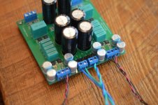
The last aspect of this design I would like to talk about is probably one of the least conventional, and it’s one that should appeal to DIY vinyl lovers. The differential topology can accommodate the standard RCA cables you usually find on the back of turntables, but in addition to this, it allows a user to run a fully shielded twisted pair all the way from the cartridge terminals to the input of this preamp. This might not seem like a big deal, but of all the sensitive areas in the playback chain, this is by far the most susceptible to picking up noise. Putting in the effort to wire this part properly pays dividends in reducing the overall system noise and improving dynamic range.
For now, let’s discuss the performance of this preamp, and in later posts I will address the best possible way to wire up the cartridge for optimal noise performance.
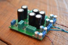
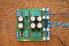
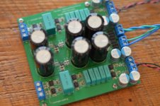
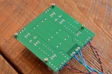
Let’s start with a few pictures of the completed PCB, and I’ll follow up with some measurements of the finished board in the next post!
I have compiled all the details and links to schematics / BOMs on the Wiki page here under section 3.4:
The Wire - All Boards and Kits Explained Here! - diyAudio
The link to purchase boards is at the bottom of the phono section on the Wiki if anyone happens to be interested
Regards,
Owen
http://www.diyaudio.com/forums/showwiki.php?title=The_Wire_-_All_Boards_and_Kits_Explained_Here
Hi Guys,
It has been a while since I’ve posted a completely new project, but I have been working away on a variety of fun things in the background. This one, in particular, I felt was worth sharing as I’ve been enjoying it immensely and I think others will too!
What I’ve gone for is a clean and simple 3-stage fully balanced phono preamp with passive RIAA nested between the first and second, and second and third stages. Here are my design criteria:
1. Above all, it must be a low noise design even with high gain (60dB @1kHz) for LOMC cartridges.
2. The RIAA curve must be very accurate.
3. Must have low distortion.
4. Needs plenty of overhead for wide dynamic range.
5. Needs to easily accommodate MC or MM parts and provide proper loading.
To accomplish requirement number one, my reference design uses on of my favorite op-amps, the LME49990, but you could build this with pretty much any single op-amp your heart desires. The LME49990 has an extremely low input noise density of 0.9nV along with unrivalled distortion performance and very high PSRR. I also opted for a three stage design which allows each individual stage to have lower gain than a single-stage or two-stage topology. Finally, it’s impossible to achieve low noise without a very good supply, so I turned to a pair of LT3042 regulators to provide an extremely quiet +/-16V supply to the op-amps. This has all been layed-out on a very clean 4-layer PCB with full ground planes and ideal shielding of all critical signals. Finally, there’s the differential topology itself which I will discuss a little later.
For my second requirement, the passive RIAA stages are designed specifically to be extremely accurate, while using simple off-the shelf parts from Mouser or Digikey that don’t cost a fortune. The accuracy comes from selecting the values to accommodate available 1% film capacitors, and using multiple parallel caps to reduce tolerance and simplify matching if desired. This is done in conjunction with 0.05% thin film resistors, and the resulting RIAA curve is an incredible +/-0.05dB from 20Hz to 20kHz without any matching of components whatsoever.
Requirement number three is met thanks to the very low distortion op-amps, and the RIAA loads designed specifically to keep the op-amps under ideal operating conditions. The op-amps also fulfill requirement number 4 by being able to run at +/-18V if desired, and having a fully differential design means they can swing over 22VRMS at the output without clipping!
Finally, I have left some open component slots for easy loading of either MM or MC cartridges to fulfill requirement number five. The user can add whatever resistive or capacitive load they might need.
The last aspect of this design I would like to talk about is probably one of the least conventional, and it’s one that should appeal to DIY vinyl lovers. The differential topology can accommodate the standard RCA cables you usually find on the back of turntables, but in addition to this, it allows a user to run a fully shielded twisted pair all the way from the cartridge terminals to the input of this preamp. This might not seem like a big deal, but of all the sensitive areas in the playback chain, this is by far the most susceptible to picking up noise. Putting in the effort to wire this part properly pays dividends in reducing the overall system noise and improving dynamic range.
For now, let’s discuss the performance of this preamp, and in later posts I will address the best possible way to wire up the cartridge for optimal noise performance.
Let’s start with a few pictures of the completed PCB, and I’ll follow up with some measurements of the finished board in the next post!
I have compiled all the details and links to schematics / BOMs on the Wiki page here under section 3.4:
The Wire - All Boards and Kits Explained Here! - diyAudio
The link to purchase boards is at the bottom of the phono section on the Wiki if anyone happens to be interested
Regards,
Owen
Attachments
Last edited:
Next up, let’s take a look at measured performance:
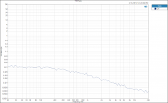
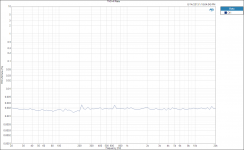
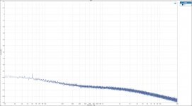
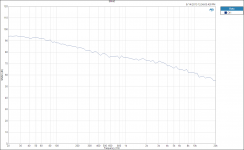
1. Here we can see the noise floor of the amp with inputs floating. The noise floor follows the RIAA curve as you’d expect giving a noise floor at about -100dB down at 20Hz, closer to -116dB at 1kHz dropping down to -135 at 20kHz. This is pretty respectable for a preamp with 80dB of gain at 20Hz! There are absolutely no correlated noise spikes save for the tiny 6dB peak at 60Hz, and this is likely being picked up by the input, and not actually local to the amp.
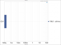
2. This is a single number measurement of the output noise, unweighted from 20Hz to 40kHz. We’re looking at just under 200uV RMS noise.
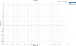
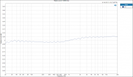
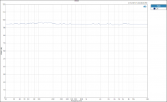
3. Here we can see the RIAA curve deviation. This is corrected using the inverse RIAA values provided by Audio Precision. I personally have never seen a phono preamp hit the RIAA curve this accurately. You’re looking at +/- 0.05dB variation from 10Hz to 20kHz.
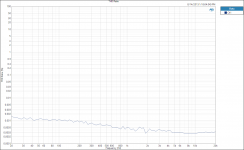
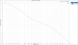
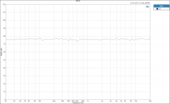
4. Here is the full un-corrected frequency response of the preamp.
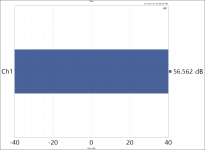
5. 1kHz Gain – 56.5dB – about right for a Denon DL-102 with 0.47mV output.
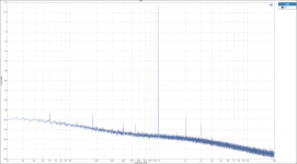
6. Here we have the FFT of the output with a 1kHz input. This shows the noise floor in operation, and the distortion profile of the preamp. There are a few additional correlated noise peaks, but these are being caused by the AP output. They are usually down at -160dB if you do a loopback with the AP itself, but thanks to 70dB of gain they are now above the noise floor. As you can see, the second harmonic is extremely low at -113dB below the fundamental, and the and the third harmonic is down 120dB. The fourth harmonic is just barely visible and there are no higher order harmonics.
All the following measurements are RIAA corrected, meaning they were performed with RIAA corrected input signals. In other words, the output levels were held constant by varying the input level over frequency. This is one way to measure an RIAA preamp, and I will provide the uncorrected curves as well in case you don’t like this")
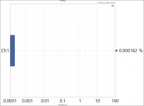
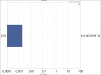
7. THD Ratio at 1mV input – representative of an MC cartridge. Note that noise interferes with this measurement at lower frequencies. This is because the AP cannot distinguish between noise and distortion if the noise level is the same as the distortion.
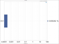
8. THD Ratio at 6mV input – representative of an MM cartridge.
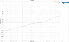
9. THD+N Ratio at 1mV input – representative of an MC cartridge.
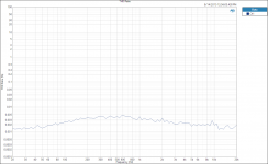
10. THD+N Ratio at 6mV input – representative of an MM cartridge.
That’s it for the first batch, so it’s on to more measurements in the next post!
Regards,
Owen
1. Here we can see the noise floor of the amp with inputs floating. The noise floor follows the RIAA curve as you’d expect giving a noise floor at about -100dB down at 20Hz, closer to -116dB at 1kHz dropping down to -135 at 20kHz. This is pretty respectable for a preamp with 80dB of gain at 20Hz! There are absolutely no correlated noise spikes save for the tiny 6dB peak at 60Hz, and this is likely being picked up by the input, and not actually local to the amp.
2. This is a single number measurement of the output noise, unweighted from 20Hz to 40kHz. We’re looking at just under 200uV RMS noise.
3. Here we can see the RIAA curve deviation. This is corrected using the inverse RIAA values provided by Audio Precision. I personally have never seen a phono preamp hit the RIAA curve this accurately. You’re looking at +/- 0.05dB variation from 10Hz to 20kHz.
4. Here is the full un-corrected frequency response of the preamp.
5. 1kHz Gain – 56.5dB – about right for a Denon DL-102 with 0.47mV output.
6. Here we have the FFT of the output with a 1kHz input. This shows the noise floor in operation, and the distortion profile of the preamp. There are a few additional correlated noise peaks, but these are being caused by the AP output. They are usually down at -160dB if you do a loopback with the AP itself, but thanks to 70dB of gain they are now above the noise floor. As you can see, the second harmonic is extremely low at -113dB below the fundamental, and the and the third harmonic is down 120dB. The fourth harmonic is just barely visible and there are no higher order harmonics.
All the following measurements are RIAA corrected, meaning they were performed with RIAA corrected input signals. In other words, the output levels were held constant by varying the input level over frequency. This is one way to measure an RIAA preamp, and I will provide the uncorrected curves as well in case you don’t like this
7. THD Ratio at 1mV input – representative of an MC cartridge. Note that noise interferes with this measurement at lower frequencies. This is because the AP cannot distinguish between noise and distortion if the noise level is the same as the distortion.
8. THD Ratio at 6mV input – representative of an MM cartridge.
9. THD+N Ratio at 1mV input – representative of an MC cartridge.
10. THD+N Ratio at 6mV input – representative of an MM cartridge.
That’s it for the first batch, so it’s on to more measurements in the next post!
Regards,
Owen
Attachments
-
 THD Ratio RIAA CORRECT 1mV.PNG52.8 KB · Views: 222
 -
 THD Ratio RIAA CORRECT.PNG50.8 KB · Views: 183
 -
 THD+N Ratio RIAA CORRECT 1mV input.PNG49.8 KB · Views: 178
 -
 THD+N Ratio RIAA CORRECT.PNG49.3 KB · Views: 201
 -
 FFT 10mV 1K.PNG124.1 KB · Views: 245
 -
 Gain @ 1kHz.png29 KB · Views: 228
 -
 RIAA CURVE.PNG49.8 KB · Views: 239
 -
 RIAA Accuracy.PNG51.7 KB · Views: 246
 -
 RMS Level No Input.PNG84 KB · Views: 310
 -
 FFT No Input.PNG121.1 KB · Views: 622
Let’s cover the rest of the measurements:
1. Here’s the corrected SINAD measurement for 1mV input – representative of an MC cartridge.
2. Here’s the corrected SINAD measurement for 10mV input.
Now let’s move on to the uncorrected measurements:
3. Uncorrected SINAD at 1mV input – representative of an MC cartridge.
4. Uncorrected THD Ratio at 1.5mV
5. Uncorrected THD+N Ratio at 1.5mV
6. Single Point THD Ratio at 1kHz 10mV input
7. Single Point THD Ratio at 5kHz 20mV input
8. Single Point THD+N at 100Hz 3.5mV input
9. Single Point THD+N at 500Hz 11mV input
10. Single Point THD+N at 1kHz 10mV input
Tomorrow I will post about some implementation suggestions, and some more details on the input wiring arrangement.
Comments, suggestions and criticism are welcome in the meantime
Regards,
Owen
Attachments
-
 THD Ratio 5kHz 20mV.PNG82.8 KB · Views: 104
 -
 THD+N Ratio 100Hz 3.5mV.PNG83.5 KB · Views: 101
 -
 THD+N Ratio 500Hz 11mV.PNG83.7 KB · Views: 96
 -
 THD+N Ratio 10mV 1K.PNG83.2 KB · Views: 103
 -
 THD Ratio 1kHz 10mV in.PNG81.7 KB · Views: 104
 -
 THD+N Ratio 1.5mV input.PNG52.2 KB · Views: 117
 -
 THD Ratio - 1.5mV input.PNG51.4 KB · Views: 120
 -
 SINAD 1mV.PNG53 KB · Views: 141
 -
 SINAD RIAA Correct 10mV.PNG50.6 KB · Views: 160
 -
 SINAD RIAA CORRECT 1mV.PNG51.1 KB · Views: 197
Looks nice opc! What's the source impedance of the Audio Precision in the 6 mV measurements? If I'm not mistaken the high-ish source impedance of an MM cartridge along with the bipolar inputs of the LME49990 op-amps would degrade the noise performance. It'd be awesome if you could do measurements with JFET op-amps like the OPA827 in the front-end and a higher source impedance to simulate MM cartridges more accurately. I'd really be interested in those.
Looks nice opc! What's the source impedance of the Audio Precision in the 6 mV measurements? If I'm not mistaken the high-ish source impedance of an MM cartridge along with the bipolar inputs of the LME49990 op-amps would degrade the noise performance.
A trick I used when measuring my MM preamp is to put an MM cartridge (generously donated by one of the members here) in series with the input. The generator impedance is pretty low (ca. 50R), so is negligible compared to the cartridge's (ca. 1k in series with 500mH).
Hi Guys,
I do plan on running some system level measurements with both MM and MC cartridges a little later on, so it would be easy to run the test as SY describes.
I probably won't get around to running this for a few weeks as it requires setting up the TT for two different carts, and tweaking the phono preamp for MC and then MM setups.
Since I have that HiFi test record here, I can run complete system THD and THD+N measurements using the 1kHz test tones. Should be fun!
In the meantime, I can simulate an MM load on the input with a 1K resistor, and change the loading and gain to be more MM appropriate. That should be pretty easy to do without too much fussing around.
I would also be open to trying a FET input op-amp, especially for MM setups. Do you guys have any particular favorites other than the OPA827? I would be very interested to see if this really makes any difference. I did a lot of experimenting with discrete parallel JFET input stages and very high performance current sources, and I never could match the performance of the LME49990 in terms of noise.
Thanks for the comments so far!
Regards,
Owen
Since you know the in of your opamp and a typical impedance of an MM, the approximate calculation of whether than current noise is significant is fairly straightforward. I'd divide the audio bandwidth into 5 or 6 segments and use an average impedance for each segment (analogous to the RIAA noise calculator on my website). For simplicity, just use 47k as an input impedance to get the order of magnitude of that noise contribution.
When time permits, I may add an option to my spreadsheet to plug in voltage and current noise density figures to get an overall s/n.
When time permits, I may add an option to my spreadsheet to plug in voltage and current noise density figures to get an overall s/n.
Nice job, Owen! A few questions/concerns:
In looking over your post in this thread, the schematic, and the wiki, I am confused as to what the operating rail voltage is. I'm seeing +/-10V, 12V, and 16V!
I'm guessing that is actually +/-12V, given your suggestion for a transformer with dual 12V secondaries in the wiki, but then the primary filter caps should be 25V parts as the 16V parts will be running at their maximum.
For the filter caps themselves, 12,000uF really seems like complete overkill...nothing wrong with it, but I would probably go for smaller value/higher working voltage parts.
Finally, what is the LF cutoff set for? 500uF output coupling caps seem far larger then they need to be. A smaller value could conceivably get you out of the requirement for back to back electrolytics. I understand these areas can all be changed at will by the builder and I respect that it comes down to personal preference, just being curious!
Thanks!
Nice job, Owen! A few questions/concerns:
In looking over your post in this thread, the schematic, and the wiki, I am confused as to what the operating rail voltage is. I'm seeing +/-10V, 12V, and 16V!
I'm guessing that is actually +/-12V, given your suggestion for a transformer with dual 12V secondaries in the wiki, but then the primary filter caps should be 25V parts as the 16V parts will be running at their maximum.
For the filter caps themselves, 12,000uF really seems like complete overkill...nothing wrong with it, but I would probably go for smaller value/higher working voltage parts.
Finally, what is the LF cutoff set for? 500uF output coupling caps seem far larger then they need to be. A smaller value could conceivably get you out of the requirement for back to back electrolytics. I understand these areas can all be changed at will by the builder and I respect that it comes down to personal preference, just being curious!
Thanks!
Answering one of my own questions, the value of Rset on the schematic results in a +/-10V rail. At the risk of possibly requiring a less standard transformer secondary voltage, I would probably scale all part working voltages accordingly and run at +/-15V rails (Rset=150 ohms). The improvement in overload margin is probably well worth it!
Hi Ungie,
You are absolutely correct that it's better to have the additional overload headroom, so running +/-15V supplies is probably the best compromise. I will tidy up the literature to reflect this in the next day or two. For my original version I just settled on +/-10V without really thinking about it. Ultimately, it's up to the user to pick what they might want, but I'll suggest 15V by default. If you happen to have mains that vary quite a bit, then you might need to run the rails a little lower to not exceed the maximum input voltage on the LT3042 and still have a few volts of headroom from the regulated to unregulated supply.
Regards,
Owen
Since you know the in of your opamp and a typical impedance of an MM, the approximate calculation of whether than current noise is significant is fairly straightforward. I'd divide the audio bandwidth into 5 or 6 segments and use an average impedance for each segment (analogous to the RIAA noise calculator on my website). For simplicity, just use 47k as an input impedance to get the order of magnitude of that noise contribution.
When time permits, I may add an option to my spreadsheet to plug in voltage and current noise density figures to get an overall s/n.
Hi SY,
I spent some time working this out, and I've concluded that if cartridges and phono preamps had facebook pages, their relationship status would have to be "it's complicated"
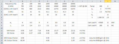
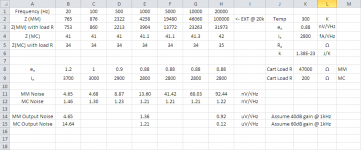
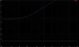
I've attached the details here as a series of images. I started by measuring the input impedance of both an MM and MC cartridge (Goldring Elektra and Denon DL-103) using a DATS V2. The MC cartridge is easy and represents a flat impedance of about 41 ohms from 20Hz to 20kHz. The MM is not so easy and varies from about 765 ohms at 20Hz up to 46kohms at 10kHz (I had to extrapolate for about 100kohms at 20kHz since the DATS can't measure that high).
Those values need to be put in parallel with the Rload in the preamp itself, so assume 200 ohms for the MC and 47kohms for the MM. This results in a final value of total Ri at each frequency that we can use for our noise calcs.
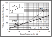
In addition to the above variable resistance, the voltage noise and current noise of the op-amps varies with frequency, so that also needs to be accounted for. The LME49990 is fully spec'd with voltage and current noise over frequency, but the OPA827 lacks the graph for current noise over frequency. I extrapolated based on the graph for the LME49990, but it really makes no difference at low frequencies where the current noise tends to contribute less thanks to the lower impedance of the MM cartridge at low frequencies.
Finally, adding to all the above, is the relative gain applied at each frequency thanks to the RIAA curve. This means we're far more input-noise sensitive at low frequencies than we are at high frequencies thanks to the ~40dB difference in applied gain.
So where does that leave us? Well, for MC cartridges the LME49990 is by far the best option having on average about 11dB less noise across the audio band at the output of the phono preamp. For MM cartridges, you are better off with the OPA827, but not by as much as you might think. At 20Hz, the LME49990 has about 3.5dB less noise, at 1kHz the OPA827 has about 3.6dB less noise, and at 20kHz, the OPA827 has about 12dB less noise, but total noise is quite low at that frequency anyhow, so it's of less consequence.
If you factor in some weighting for hearing sensitivity over frequency, then the OPA827 is probably the better choice at the end of the day even if it has higher noise at low frequencies.
So, based on the above, it's probably safe to say that if you're using a MM cartridge, the OPA827 should be used in the first stage only, and if you're using an MC cartridge, you should definitely use the LME49990 for all stages. If you frequently swap between MM and MC, then stick with the LME49990 for all stages.
Let me know if all this looks right!
Regards,
Owen
Attachments
It's kind of what I expected to see, but I'm now motivated to incorporate input current and noise voltage densities into my calculator to see if I get the same result. My assumption will be EQ between first and second stage, so it would have to be modified if the EQ is split.
I wouldn't think that the opamp type for the second stage would be critical, since its noise is uncorrelated with the input stage and the phono cartridge noise, so would tend to disappear in the RMS summing. But I haven't done the calculation, so this is sheerly pulled out of my hind regions.
I wouldn't think that the opamp type for the second stage would be critical, since its noise is uncorrelated with the input stage and the phono cartridge noise, so would tend to disappear in the RMS summing. But I haven't done the calculation, so this is sheerly pulled out of my hind regions.
I would also be open to trying a FET input op-amp, especially for MM setups. Do you guys have any particular favorites other than the OPA827?
The LME49880, the FET input cousin of the LME49990. It is a dual rather than a single though.
Figure 1 in the data sheet is current noise and voltage spectral density vs. frequency. From about 600Hz and up the voltage noise density graphs of the LME49880 and OPA827 look pretty identical. Below 600Hz though the 49880 is noiser, at least for voltage noise.
Last edited:
Hi agdr,
I plugged both the OPA627 and the LME49880 into my spreadsheet, and neither come out looking too great.
Both have much higher levels of voltage noise at low frequencies which makes them quite a bit noisier than the other options. Neither would be at all suitable for MC, and both are a little worse than the OPA827 for MM duty. All three are almost exactly equivalent above 1kHz, but below that the OPA827 really pulls away.
I had a little poke around and found the LT1028 which looks like it might be the best candidate overall for both MM and MC. For MM applications it outperforms the OPA827 everywhere below 1kHz, and only slightly under-performs it above 1kHz. Since noise is more critical lower in frequency, I'd give the win to the LT1028. For MC applications, there's no contest. It has the lowest overall voltage noise which means it just slightly outperforms the LME49990 and absolutely destroys the OPA827. The problem is that they don't spec any THD+N numbers under our conditions, so that's up in the air.
I would say that for a phono preamp specifically, the noise is really the most critical metric for choosing an op-amp. I would take lower noise over lower distortion since the distortion from the cartridge and arm is already pretty high as it is. For a headphone amp, I would say the opposite. The gain is generally low making noise less of a problem, and the sources and transducers tend to have very low distortion, so I would prioritize THD over noise in those applications.
I've attached my spreadsheet if anyone wants to play with it. The yellow boxes are user inputs, the green boxes should not be touched. Only change the cartridge resistance values if you know what they are for your specific cartridge. I changed the extension to .txt, so you'll need to change it to .xlsx before opening it.
Regards,
Owen
Attachments
OK so we have discussed opamp types almost completely. As we all know it is a roll your own world. Now I would like to hear more on the differential connection possibilities. That seems to make all the sense in the world when it comes to a phono stage! Thanks for the excellent thread
Thanks SY. Where can I find those? Link if possible.
One is in the articles section of this website. "His Master's Noise" MC preamp. The other was published in Linear Audio, volumes 7 and 8.
- Status
- This old topic is closed. If you want to reopen this topic, contact a moderator using the "Report Post" button.
- Home
- Source & Line
- Analogue Source
- The Wire Balanced Phono Preamp