Hi Guys,
AndrewT:
You make me out to be an evil troll
You are correct, I took a quick glance at the datasheet and should have looked closer.
The 2SJ162 and 2SK1058 do indeed appear to be lateral devices and should work with this amplifier. I'm not going to make any guarantees since I don't have any here to test, but you should be alright to use them.
Sorry I jumped to the opposite conclusion, my bad.
NMOS:
Easy there tiger... that was a little harsh. I don't agree with removing safety features either, but he's free to his opinion, and he's free to do as he pleases with his amplifiers.
Anyone else here looking to remove fuses or any other safety feature should really consider the possible consequences. Burning your house down isn't a funny prospect, and that's exactly the sort of thing those devices are designed to protect against.
Unless you fully understand the risks, and understand that you're putting your life and possessions on the line, then you should never mess with safety devices.
Qrikard:
I can add that muting option at the top as there's plenty of room up there and there's no cost impact.
As for the routing, I basically made an irrelevant signal (the voltage to the mute pin) a little worse in order to keep it as far away from the inputs as possible. If someone opts for a non regulated supply that happens to be noisy, that line could have some noise on it, so I wanted it on the other side of the ground plane while it crossed over the inputs.
If you can get enough people interested in the supply, then I think it's a great idea. You can count me in for two if the voltage and power rating lines up with what I'm looking for.
As for performance, it's really hard to say without knowing the specs on the PSU. Are the outputs regulated? How much ripple is specified? One of the huge advantages to an SMPS is that they often have very little 120Hz noise, but instead push the ripple further up in frequency and often well outside the audio band which is a very good thing.
I might just order one of them and give it a try for fun.
If you can get a custom unit with the voltage for the mosfets and the front end, and if the noise is respectable, then to me it's really a no-brainer.
Cheers,
Owen
@ Ian:
right, so not only are you taking risks and playing fast and loose with your life, but that of others as well? 1000va toroid on a dac? that much stray fields in a low level cct when its not needed; vast life changing differences or not, cannot be good. also making such posts regardig defeating safety and soldering direct to the wall, thus promoting it due to improvement is imo irresponsible and i would thing against the rules of the forum
@ opc: have you posted any psrr numbers? I havent got toroids yet either, so depending on that and the noise spec of the smps i might be keen as well, only if it has the 2 different voltages though
Last edited:
opc,
Bob Cordell's balanced input adaptor
http://www.diyaudio.com/forums/soli...-complementary-input-stage-4.html#post1305166
Please put me in for 4PCBs and 2component kits, i.e. 2complete kits, including PCBs and 2 extra PCBs, as agreed by pm.
Bob Cordell's balanced input adaptor
http://www.diyaudio.com/forums/soli...-complementary-input-stage-4.html#post1305166
Please put me in for 4PCBs and 2component kits, i.e. 2complete kits, including PCBs and 2 extra PCBs, as agreed by pm.
@ qusp:
If stray field is what is takes to make superb Hi-Fi then fine.
I was professionally installing for customers, including professional studios and personal friends, dedicated super spurs for Hi-Fi that were fully compliant with the 16th edition of the UK's IEEE regulations. That means I know (or knew at least) what I'm doing and the're are safe.
I never said soldering to the wall. I and these people don't use 'wall sockets' but instead dedicated 'industrial' distribution fed through very high current cable. A 'serious' power amp playing loud might be trying to suck 100 amps for a tiny time period on each of the AC peaks. Hence giving each power amp it's own 100amp supply. We are not juvenile idiots (but have not forgotten when we were and still have a sense of humour) My partner in our cottage industry from the mid 90's is an ex RAF electronics technician at the time specialising in navigation and landing electronics. If he failed at his job then planes could fall from the sky, he knows how to build in safety and reliability. And he's been into Hi-Fi for at least 50 years.
If an educated capable high IQ 50 year old customer knowing exactly we're doing then asks me to solder his amp to the spur then that risk is his to take, it's still fused. You don't need 20 fuses in series to protect an amplifier. Just one will do it. It might sound better to have a fuse at each amplifier and none by the meter board in case each amp pulls from each other through the resistance of that one fuse, but should the cable be damaged and shorted it would take out the service head fuse to the property and it's a big nuisance to get those replaced in the UK. I currently have two service heads, each followed by it's own meter, I run the Hi Fi / AV room from one of those.
Also we've been known to run with scissors
If stray field is what is takes to make superb Hi-Fi then fine.
I was professionally installing for customers, including professional studios and personal friends, dedicated super spurs for Hi-Fi that were fully compliant with the 16th edition of the UK's IEEE regulations. That means I know (or knew at least) what I'm doing and the're are safe.
I never said soldering to the wall. I and these people don't use 'wall sockets' but instead dedicated 'industrial' distribution fed through very high current cable. A 'serious' power amp playing loud might be trying to suck 100 amps for a tiny time period on each of the AC peaks. Hence giving each power amp it's own 100amp supply. We are not juvenile idiots (but have not forgotten when we were and still have a sense of humour)
My partner in our cottage industry from the mid 90's is an ex RAF electronics technician at the time specialising in navigation and landing electronics. If he failed at his job then planes could fall from the sky, he knows how to build in safety and reliability. And he's been into Hi-Fi for at least 50 years.If an educated capable high IQ 50 year old customer knowing exactly we're doing then asks me to solder his amp to the spur then that risk is his to take, it's still fused. You don't need 20 fuses in series to protect an amplifier. Just one will do it.
It might sound better to have a fuse at each amplifier and none by the meter board in case each amp pulls from each other through the resistance of that one fuse, but should the cable be damaged and shorted it would take out the service head fuse to the property and it's a big nuisance to get those replaced in the UK. I currently have two service heads, each followed by it's own meter, I run the Hi Fi / AV room from one of those.Also we've been known to run with scissors
Last edited:
I think these are the developers of that device: Pro Audio - Alfet Lateral MOSFETs
Last edited:
The link to the datasheet is broken, though.I think these are the developers of that device: Pro Audio - Alfet Lateral MOSFETs
I'll go for 6 x PCB depending on the price of postage to the uk.
Ill take 3 full part kits include pcbs if you can send with boscoe order to UK? via USPS small box priority $15
Yes. Perhaps you could send them an e-mail and tell them?The link to the datasheet is broken, though.
Last edited:
Hi Guys,
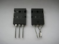
Most of those links are correct, and although the data seems to vary (16A vs. 24A) I'm convinced they're all the same parts and I think they're all diffused by Semelab. I've attached a picture of the two parts I have here so you can compare.
Here are some of the places that carry lateral fets:
Pro Audio - Alfet Lateral MOSFETs
Lateral Mosfet
TT electronics Semelab Limited - Magnatec Datasheets
Magnatec. ALFET Lateral MOSFETs
www.class-d.com
Here's the closest thing I can find to the correct datasheet:
http://products.semelab-tt.com/pdf/magnatec/ALF16N16W ALF16N20W.pdf
http://products.semelab-tt.com/pdf/magnatec/ALF16P16W ALF16P20W.pdf
Cheers,
Owen
Attachments
Last edited:
@opc, Thanks for the addition of the header. Regarding the layout thanks for explaining and i agree that's the best option.
@IanAS, Sorry but i prefer measurements of at least blind tests and by your description it doesn't look like you did any blind A/B tests. So i'm going to go with opc's (and others) measurements on this one because i cant imagine that a 1000VA transformer can improve the sound for a low power DAC only increase cost and risks...
Regarding the SMPS i'm not qualified to make the final judgments but at the end of this thread there are some interesting measurements. Post 296 and forward. Short summary, direct measurements with probe ground clamp shows 4V p-p noise on the output of a SMPS800R. Then he modified the probe to reduce the open ground loop and the ripple reduced to 270mV p-p. This should indicate that the main problem is RFI and if the french people in the link below are right (and the google who translated) the noise is very low with a faradays cage and good implementation.
These numbers are stolen from the french thread and translated using google so don't blame me if this is completely irrelevant...
I don't know which of the SMPS versions they are using.
French thread about redusing the noise from the supply.
The first line represents what we see on the rail of the PSU
la seconde ligne ce que l'on voit en sortie d'ampli. the second line we see that the output of amplifier.
Alim Sans rien : Without power supply:
Alim : 90mV -31.2 -41 Alim: 90mV -41 -31.2
Ampli: 56mV -35.3 -41 Amp: 56mV -41 -35.3
Faraday : Faraday:
Alim : 37.5mV -45 -43 Alim: 37.5mV -45 -43
Ampli: 23mV -43 -55 Amp: -43 -55 23mV
Faraday + Selfs: Faraday + chokes:
Alim : 17mV -55 -58 Alim: 17mV -55 -58
Ampli: 20mV -50 -55 Amp: -50 -55 20mV
Faraday + cables torsadés : Faraday + twisted cables:
Alim : 32mV -48 -44 Alim: 32mV -48 -44
Ampli: 14mV -50 -55 Amp: -50 -55 14mV
My hopes are good for these supplies but it seems that a faradays cage is mandatory. These measurement should be on the main rail and the regulated voltage is hopefully better. Otherwise it might be possible to ask for 15V over the main voltage for the front end so we can have an extra regulator close to the boards.
I have sent an email to Cristi and hopefully he will reply soon or maybe even drop in here (sent link and request).
Could Cristi make this for us? I assume it is 'just' a grounded metal braid encapsulating the PSU.My hopes are good for these supplies but it seems that a faradays cage is mandatory.
Cheers,
Nic
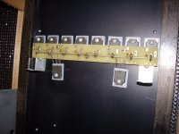
They wait and wait and one day a circuit might join them...a rats nest of wires hanging off the end of a very high BW amplifier
Just the two supply wires and the two gate wires and the output to join on.
The 9th and 10th were just to see if they fit neatly. I think they do
The plan is to affix the 6 or 8 main res caps on a support board just over the mosfets so the ± wires are as short as possible.
The circuit was to fit between the lower two mosfets.
The 1000VA bolts just up from there to a standoff plate (leaning on the left in the pic).
Attachments
Last edited:
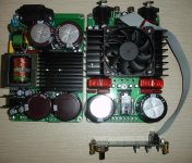
Hi Guys,
I had a good read through the documentation for the SMPS800R. I didn't realize there was an entire pdf with several more details and a basic PCB layout.
Overall, I like the supply, but I do have a few concerns. The lack of an inductor on the output rails is a bit of a mystery to me, and it must result in relatively high ripple on the output.
I would say that the addition of an inductor would almost be a must, along with another set of large storage caps. Ideally, it would be best to have the inductors on board since that would be better from an EMI point of view. They should be placed immediately after the rectifiers and before the caps. Something in the neighborhood of 18-20uH should do the trick.
The higher voltage supply should be no problem to implement since it looks like it's just another tap on the secondary of the transformer along with a full bridge, some caps and a pair of regulators. Adding a few more turns on either side of the high power secondary winding should be a piece of cake, and that would give the extra HV supply to the regulated section.
I'm looking forward to more details when you guys hear something.
Cheers,
Owen
Dear fellows, I was kindly suggested by QRikard to take a look at this thread and provide a solution for suppliyng this great amplifier. First thing which came ino my mind was a a modifies SMPS500, but after reading few posts i realized that it won't be bad if the power supply would include few more protections, such as shut down when DC component is detected at the output of the amplifier, or a shielded case to contain as much as possible the EMI.
Before i can propose a suitabe topology, please allow me to read the thread througly, and reply few hours later. Any suggestions and ideas are wellcome.
Sent from my ASUS eee Transformer
Before i can propose a suitabe topology, please allow me to read the thread througly, and reply few hours later. Any suggestions and ideas are wellcome.
Sent from my ASUS eee Transformer
Cristi, thanks for stopping by. Looking forward to your suggestion, i like the sound of additional protection.
@opc, i know it's late but if someone backs out could you sign me up for one more kit and if possible an extra board? So in total 3 kits and 5 PCB (or just 4 boards as currently).
Transistors and LME for the leftover board(s) would be nice if you can consider making an exception from the kits. I think i will have a big problem to find those in the future since i can't find them at any local supplier today.
@opc, i know it's late but if someone backs out........
OK, I back out completely. Changed plans and looking for a high quality 10-20 W pure class A amplifier. I thought of the LME design being a nice and "easy" but temporarily solution as I am more into tubes; will concentrate on Ciuffoli's hybrid design now, or eventually a 300B SE design. Good luck with the project!
Hi Guys,
Alright... I transferred 1 of pieter t's boards to QRikard, and I'll keep the single as a development board so I'm not experimenting on any of my boards.
Cristi:
Thanks for stopping by! If you need anything at all let me know, and hopefully we can work towards a solution that is well tailored to the amp.
After reading your documentation on the SMPS800R I would suggest the following:
- Adding 18-20uH inductor immediately after the diodes and before the output filter capacitors. (24 turns of 16AWG on Kool u 77932)
- Look into using Fairchild Stealth diodes on the output of the main supply (FFH15S60STU)
- Replace each single large bulk output cap with 4 or 6 UCC KZE series 820uF, 100V parts (EKZE101ELL821MM40S) (565-1746-ND)
- Add a high current common mode ferrite filter at the output with some good SMD 0.01uF caps both sides.
All of these suggestions aim to reduce ripple on the output of the supply, and although they might add a little to the cost, I think it would drastically improve ripple performance and reduce EMI issues.
Let me know what you think.
Cheers,
Owen
SMPS800R
The topology used for SMPS800R, SMPS500R, SMPS300R and SMPS2000R is LLC resonant converter where the primary switches are soft commutated, at nearly zero voltage and secondary diodes are commutated at zero current.
One of the main advantages of using this topology is that it does NOT require an inductor on the secondary side, between the rectifiers and capacitors, and adding an inductor would worsen the performances as would be seen as another series inductor with transformer from the primary side and would affect the resonant tank parameters. Another important advantage is that the maximum voltage on the secondary diodes does not exceed 2x the output voltage for the single output version and the nominal voltage for +- version. This would greatly reduce their voltage stress, allowing lower voltage rating diodes to be used. Also the diodes are switched at zero current, reducing the current stress. For SMPS300R, SMPS500R versions with output voltage up to +-60V i used Shottky diodes only, given the fact that their reverse recovery charge is nearly zero, and the forward voltage drop is very low, under 1V and tipically 0.6-0.7V for 100V devices. The suggested diode would be only be suitable for high output voltages, above 150-200V on each rail, as it's Vf is higher, 2.1V
When i designed the SMPS800R the main use was to be paired with a TA3020v3d amplifier module, to build a compact amplifier. Both boards have same size, 100x150mm and the empty space next to the SMPS800R IEC connector was used install the speaker output terminals. The supply cable from the power supply to the amplifier would use a ferrite bead 16x30mm similar with those used for computer monitors signal cables, which would be a very effective common mode filter. The choice of the secondary side capacitors was made based on the highest capacitance per volume ratio, and i found that using a single large cap would give more capacitance than several smaller ones.
For the current project, i consider designing a power supply from scratch, and beside the LLC topology, a simple QR half bridge might be used as well. With both topologies are advantages and disadvantages, and i will try to expose them in a future post and disuse upon then before deciding which one should be used.
Attachments
- Home
- Amplifiers
- Solid State
- "The Wire AMP" Class A/AB Power Amplifier based on the LME49830 with Lateral Mosfets