why the wire amp doesnt include the zobel network at the output? Is it very stable even without it?
http://sound.westhost.com/ad_fig10.gif
http://sound.westhost.com/ad_fig10.gif
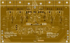
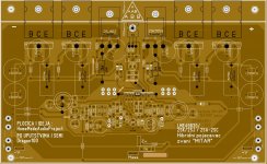
Ordering details are in this thread - http://www.diyaudio.com/forums/vend...jects-available-here-bal-bal-se-se-lpuhp.html There are no kits anymore, too much hassle for almost zero return for Owen and no volunteers have put their hands up for arranging group buys of parts, but the order lists are pretty clear and easy to get parts for yourself.
Chris
Thank you. I may organize a bulk order of parts, put my teenagers (son and daughter) to work and bundle parts kits together. I will ask OPC to ensure he (or no one else) has concerns/issues with doing so. I would only need enough commitment for 10 or so stereo parts kits to get the best discount and pay my children for packaging. My son already mentioned if I do this he wants me to build him a stereo amplifier for payment.
I will think about it, map out the logistics and run some numbers.
Thank you for the link. It was not an easy task to wade through so many comments on the page to find the information I sought.
Darren
I have created a BOM in Mouser project manager, it has been shared, so you can use it to order parts.
Let me know if you have any ?'s. You will see some optional components and extras(bulk discounts) in the BOM, you can decide if you do not want to order them. The orig. OPC BOM was not 100% complete, as insulators were missing. IIRC the only thing not present are the Lafets, I got mine from Newark.
I see 647-UPW2A102MHD is on back-order. If you look at the notes for that comp, I have a sub 647-UPS2A102MHD listed, it is in stock at this time. I am sure there are other sub's as well but I have not investigated them.
Notes from Mouser
When you are ready to access your project again you can do so by using either of the following 2 methods:
1. Save the link listed below and enter that link into your web browser at anytime.
http://www.mouser.com/ProjectManager/ProjectDetail.aspx?AccessID=d36806234b
2. Go to our EZ Buy page and enter your project Access Number listed below where you see Enter Your Access ID.
Enter Access ID: d36806234b
Last edited:
I have created a BOM in Mouser project manager, it has been shared, so you can use it to order parts.
Let me know if you have any ?'s. You will see some optional components and extras(bulk discounts) in the BOM, you can decide if you do not want to order them. The orig. OPC BOM was not 100% complete, as insulators were missing. IIRC the only thing not present are the Lafets, I got mine from Newark.
I see 647-UPW2A102MHD is on back-order. If you look at the notes for that comp, I have a sub 647-UPS2A102MHD listed, it is in stock at this time. I am sure there are other sub's as well but I have not investigated them.
Notes from Mouser
When you are ready to access your project again you can do so by using either of the following 2 methods:
1. Save the link listed below and enter that link into your web browser at anytime.
http://www.mouser.com/ProjectManager/ProjectDetail.aspx?AccessID=d36806234b
2. Go to our EZ Buy page and enter your project Access Number listed below where you see Enter Your Access ID.
Enter Access ID: d36806234b
Excellent! Thank you. That is a great start and a possible end-to-end solution. Thank you very much for sharing this.
Darren
did anyone try to see how clipping looks on lme49830 based amplifier, sinus signal 12-20khz?
.
i tried it and it clips non-symetrical (negative rail clips about 3V earlier),and in my case it slightly oscilates from peak of positive signal toward to zero point on osciloscope.
.
i tried it and it clips non-symetrical (negative rail clips about 3V earlier),and in my case it slightly oscilates from peak of positive signal toward to zero point on osciloscope.
a man named Dragan100 in our Serbian forum has developed a schematics for this IC and my idea was driving mosfet hybrid BJT output stage.
i have drawn two pcb by his instructions,one for IRFP240/9240 and second for 2SJ162/2SK1058 and and they both work well,sound well and they both were connected to 8r60uH470nF load and proven them selves to be stabile amplifiers.
the thing is that i have tested them at 15kHz sinus wave and cliping for 2sk/2sj looks just like on pictures from posts you linked,but for IRFP240/9240 it has some sinusoidal form at the same place that lateral vesion has that almost vertical fall.
i have seen a schematics at about 30 pages earlier,i believe that it is being used in this thread and as i could see you used 220-330Ohm gate-resistors with lateral mosfets,and there is no resistor between gate and source. we used it in both versions,but the result is not equal and now i am looking for experinences from other people before i go and try to do same changes.
Dragan100 and i did it like this-
Attachments
a man named Dragan100 in our Serbian forum has developed a schematics for this IC and my idea was driving mosfet hybrid BJT output stage.
i have drawn two pcb by his instructions,one for IRFP240/9240 and second for 2SJ162/2SK1058 and and they both work well,sound well and they both were connected to 8r60uH470nF load and proven them selves to be stabile amplifiers.
the thing is that i have tested them at 15kHz sinus wave and cliping for 2sk/2sj looks just like on pictures from posts you linked,but for IRFP240/9240 it has some sinusoidal form at the same place that lateral vesion has that almost vertical fall.
i have seen a schematics at about 30 pages earlier,i believe that it is being used in this thread and as i could see you used 220-330Ohm gate-resistors with lateral mosfets,and there is no resistor between gate and source. we used it in both versions,but the result is not equal and now i am looking for experinences from other people before i go and try to do same changes.
Dragan100 and i did it like this-
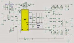
Are the compensation values good enough? I see its being reversed as instead you probably need to swap it? like C10 being 33pf and C11 being 12pf respectively?
According to the Wireamp worksheet in the first posts of the thread..
http://www.diyaudio.com/forums/atta...e49830-lateral-mosfets-wire-amp-schematic.pdf
the smaller value comes first like 12pf and then 20pf?
which one is right here?
Hi Guys,
Now that people have everything they need to start building, I have a few goodies to post up regarding bias settings and the SMPS I've measured.
I'll start with bias. I took a whole pile of distortion and distortion product ratio (DPR) measurements at various different bias levels. This way, each individual user can make their own decisions about what levels to bias at.
Here's the test setup:
Amp setup = SE
PSU = DPS400 with PBTU
+/- 52VDC on Mosfets
+/- 64V on LME
Bias levels from 25mA to 1A.
Gain = 28dB
Input = 225mV RMS
Output = 3.9W
Load = 8 ohms
The first set of attached images show the distortion product ratio at different bias currents.
Overall bias levels are (in order):
25mA
50mA
100mA
150mA
200mA
250mA
300mA
350mA
400mA
500mA
600mA
700mA
800mA
900mA
1000mA
At 52VDC on the mosfets with a bias per FET being 1A its too high dissipation about 52W. I am really surprised at the bias stability. Was the bias stable?
At 52VDC on the mosfets with a bias per FET being 1A its too high dissipation about 52W. I am really surprised at the bias stability. Was the bias stable?
It was quite stable. It seems to actually be more stable at higher bias. There is a little bit of weirdness at very low bias currents, where it will tend to drift a bit, but I don't imagine anyone building this will be biasing it at less than 100mA.
I was using a relatively large heatsink for the aforementioned tests, and I had a fan going as well to keep things reasonable. Without active cooling you would need a mighty big heatsink, and it would probably also be advisable to bend the leads on the fets such that they are mounted a little farther apart. Pd for the package is 250W@25C, so asking for 50W per device is well within the realm of safety, but the heatsinking needs to be solid. Thin mica pads with good thermal grease is also required.
Regards,
Owen
Last edited:
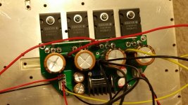
I = 350 mA, 55,5 V on mosfets and 64 V on frontstage. Dead silent without input connection but a very low hum (ear in speaker) when connected to a source or shorting the inputs. Cannot find it yet. Oscilloscope doesn't show oscillations. Zobel underneath the pcb and a coil and resistor at the outputs. I made the heatsinks for the lme a little bigger. The sound is id very good.
Some pictures:
https://www.dropbox.com/s/hfzw7bxlfeai8ob/WP_20141212_012.jpg?dl=0
https://www.dropbox.com/s/tjaf4g29y4iz3b1/WP_20150118_001.jpg?dl=0
https://www.dropbox.com/s/j0ucefflhhrz6by/WP_20150118_004.jpg?dl=0
Some pictures:
https://www.dropbox.com/s/hfzw7bxlfeai8ob/WP_20141212_012.jpg?dl=0
https://www.dropbox.com/s/tjaf4g29y4iz3b1/WP_20150118_001.jpg?dl=0
https://www.dropbox.com/s/j0ucefflhhrz6by/WP_20150118_004.jpg?dl=0
how much does each of this heatsink would dissipate?
https://dl.dropboxusercontent.com/u/7421969/2013-10-27 12.21.31.jpg
https://dl.dropboxusercontent.com/u/7421969/2013-10-27 12.21.31.jpg
Those heatsinks are massive for this amplifier and are over kill!!
It is not a case of how much power they dissipate rather what would be the temperature rise for a given amount of power. I'd say they are in the region of 0.1 degree C per W, so for 100W they would rise maybe 10C above ambient, which is hardly nothing at all = over kill
It is not a case of how much power they dissipate rather what would be the temperature rise for a given amount of power. I'd say they are in the region of 0.1 degree C per W, so for 100W they would rise maybe 10C above ambient, which is hardly nothing at all = over kill
Those heatsinks are massive for this amplifier and are over kill!!
It is not a case of how much power they dissipate rather what would be the temperature rise for a given amount of power. I'd say they are in the region of 0.1 degree C per W, so for 100W they would rise maybe 10C above ambient, which is hardly nothing at all = over kill
once I did at 52V biased per transistor at 200ma and one transistor on one heatsink and they were dissipating approx 10W and it was quite warm. Im thinking to use till 30W of dissipation for 30V and 1Amp bias for this amp. I think it will be quite hot.
each of that heatsink is 200mm in height.
- Home
- Amplifiers
- Solid State
- "The Wire AMP" Class A/AB Power Amplifier based on the LME49830 with Lateral Mosfets