
To get boards see this thread - http://www.diyaudio.com/forums/vend...jects-available-here-bal-bal-se-se-lpuhp.html
Advice needed on PSU for Wire Amp
I have some parts from an old PSU and would like to know if they would be suitable for powering a pair of "Wire" Amps (same supply for both stages of both amps) ? The parts consist of a Toroidal 100-VA transformer [25-0-25v @ 2A], a bridge rectifier and a pair of 10'000uF / 40v caps, no regulation. Not very loud I know, but would be enough?
I have some parts from an old PSU and would like to know if they would be suitable for powering a pair of "Wire" Amps (same supply for both stages of both amps) ? The parts consist of a Toroidal 100-VA transformer [25-0-25v @ 2A], a bridge rectifier and a pair of 10'000uF / 40v caps, no regulation. Not very loud I know, but would be enough?
Thanks for the clarification AndrewT. I wonder if I can tap your knowledge a little further?
It turns out that I have a choice of trafos, both 100VA, one +/-25v @ 2A, and one +/- 30v @ 1.6A. Not sure which would be best. I get how voltage effects output, but I'm not sure what would happen if there's not enough current, bearing in mind I'm hoping to power two "Wire" amps with one PSU.
Also, if I may, what sort of 'improvements' do you think I could make?
Sorry for intruding...
But if you have a 100W transformer, 100W is what you will get from it, no matter the voltage. A 100W 30V transformer will also give you the required 25V 2A + it gives you a nice head room to your cap bank during low power requests (silent parts) of your signal.
But if you have a 100W transformer, 100W is what you will get from it, no matter the voltage. A 100W 30V transformer will also give you the required 25V 2A + it gives you a nice head room to your cap bank during low power requests (silent parts) of your signal.
A 100VA transformer can power a total of 50W to 100W of maximum power.
This is for domestic listening operation.
Parties and PA need to take more heat into the equation.
If that 100VA is for two channels, then each channel will be of the order of 25W to 50W of maximum power.
Way back, I suggested, that taking account of transformer regulation, I'd always recommend that the smallest transformer for a power amplifier should be around 160VA.
I still believe that is a valid recommendation.
I am in the process of developing a small desktop active two way, with an active bass only.
This small active has only a 135VA transformer powering two 55W amplifiers. One amp is handling 150Hz to 2700Hz and the other is handling >2700Hz.
This, I hope, will be adequate since it breaks my usual rule of 160VA.
Last edited:
you are referring to a continuous maximum output.For eg, one or more class B Amplifiers with a 100W transformer & bridge rectifier & capacitors, will only get you around 70W max due to losses in the above. Any more than this = clipping
A transient output can easily exceed a nominal 50% to 80% of the transformer VA.
The smoothing capacitors supply the transient current to the speaker/s.
The smoothing capacitors initially supply full voltage current to the transient load. These smoothing capacitors immediately begin discharging as transient current is drawn from them.
If the music signal is lots of various strength transients of various lengths then the capacitors manage the current supply very well and don't deplete significantly.
We can still hit 100W of total maximum outputs frequently and not enter clipping.
We can even manage a tiny bit more than that, if the transients are short enough.
Last edited:
That will get you a +-35Vdc supply.
A little bit on the small side, but it will work.
Try it and then decide if you think if might need improving.
I agree with Andrew here, in that you really will need to try it out and see how it works for you.
One way or another, you'll get a good base for a supply and can later add to it or modify it if you find it to be insufficient.
I would suggest the following two improvements to start:
- more capacitance (this is very cheap and easy to add at the voltages we're discussing)
- A larger power transformer
As for which transformer to use, I would suggest that the answer depends primarily on the load impedance of your loudspeakers. If you're driving a 16 ohm load, you will absolutely want the higher voltage transformer. If you're driving a 4 ohm load you will absolutely want to use the lower voltage transformer.
As Andrew mentioned, you'll get somewhere in the neighborhood of 40-50W per channel into 8 ohms if your line voltage is on the higher side, and it's only for domestic use. This is probably enough if your speakers are reasonably efficient and you don't listen at very high levels for sustained periods of time.
If I were you. I'd build it up as is, give it a listen, and start by adding more capacitance if you're not happy. Additional 10,000uF caps can be had for less than $5 each, so it's a pretty cheap fix.
Way back, I suggested, that taking account of transformer regulation, I'd always recommend that the smallest transformer for a power amplifier should be around 160VA.
I still believe that is a valid recommendation.
You might need to walk me through this statement Andrew
Would you not determine the VA requirements of the transformer based on the target power output of the amplifier? If you wanted a 10W amplifier to drive a pair of 120dB/W/m horns, would that still apply? Seems like a very strange rule of thumb.
The reason I ask is that I use 30-50VA transformers on the LPUHP, which has regulated supplies and provides 16W of output power. I cannot see any reason why going to a 160VA transformer would improve matters in any way, and in fact, would only serve to increase the dissipation on the regs at higher output levels.
Sorry for intruding...
But if you have a 100W transformer, 100W is what you will get from it, no matter the voltage. A 100W 30V transformer will also give you the required 25V 2A + it gives you a nice head room to your cap bank during low power requests (silent parts) of your signal.
This statement is a little bit misleading... a transformer doesn't really work in a power envelope like that. Both the 25V and 30V transformers will probably have similar primary windings and cores, but the 30V transformer will probably use a smaller guage winding with more turns on the secondary, which ultimately will result in higher resistive losses if you try to draw the same 2A as you could get from the 25V variant which likely has a heavier guage secondary winding with fewer turns.
The result will be worse voltage regulation and lower overall power if you use the higher voltage transformer while driving a lower impedance load. For 4 and 8 ohm loads, I would suggest the 25V transformer, and for loads higher than 8 ohms, it might be best to move up to the 30V variant.
It's also worth noting that if you're driving 4 ohm loads, then the transformer will essentially become the power limiting device, which means you'll either need to fuse it appropriately so you don't overheat it under heavy use, or move to a larger transformer.
Cheers,
Owen
Thanks for all the input on this. However, I'm still a little fuzzy on the trade offs between volts and amps. There must be a point where more volts with less amps (for a given VA) becomes unusable. I can see how lower volts would lead to earlier clipping, but, and I'm guessing here, if more current is demanded than the PSU can deliver, the only thing I can think of is that the secondary coils would burn out. Or would the effect of clipping mean that the FETs wouldn't be able to draw more current than can be given? Perhaps that's why 100VA trafos don't come with voltages any higher than +/-30v.
There must be a happy balance for 8 ohm speakers at around 25W (audio power) which I'm quite happy with. So, just to confirm, for 8 ohms @ 25W it'd be best to go with the +/-25v 2A version with the option of more Farads (than the 10k I have) if I get any clipping?
Seb
There must be a happy balance for 8 ohm speakers at around 25W (audio power) which I'm quite happy with. So, just to confirm, for 8 ohms @ 25W it'd be best to go with the +/-25v 2A version with the option of more Farads (than the 10k I have) if I get any clipping?
Seb
...the 30V transformer will probably use a smaller guage winding with more turns on the secondary, which ultimately will result in higher resistive losses if you try to draw the same 2A as you could get from the 25V variant which likely has a heavier guage secondary winding with fewer turns.
I do not entirely share the opinion on this, although I see your point.
Note that i am not trying to draw 2A from the 30V transformer. Im trying to draw the 100W from it. The cap bank takes care of the amps needed by the amplifier. Transformer is just topping the bank with all of its 100W... IMHO
The result will be worse voltage regulation and lower overall power if you use the higher voltage transformer while driving a lower impedance load...
The worse regulation does not matter (IMO). I will still have (hopefully) voltage headroom in the bank. If I dont, I have exceeded the 100W transformer limit. I would also loose the regulation the same way if I exceeded the 25V transformers limits.
In my opinion the (only thinkable) trade off with higher rail voltages will be because of the BIAS in the amplifier. Not necessarily only because of the speaker impedance.
One will waste more power as heat up in the air, if one do not turn the bias down accordingly - which one probably would not like to do, to keep the excellent amplifier in its excellent bias region. That heat will be directly off of the tranformer power. And cant be used to power the speakers - what a waste...
But thats just my opinion.
Thanks for all the input on this. However, I'm still a little fuzzy on the trade offs between volts and amps. There must be a point where more volts with less amps (for a given VA) becomes unusable. I can see how lower volts would lead to earlier clipping, but, and I'm guessing here, if more current is demanded than the PSU can deliver, the only thing I can think of is that the secondary coils would burn out. Or would the effect of clipping mean that the FETs wouldn't be able to draw more current than can be given? Perhaps that's why 100VA trafos don't come with voltages any higher than +/-30v.
Hi Seb,
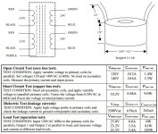
Perhaps the attached Antek datasheet will help clarify a few things. Generally speaking, the transformer manufacturer will specify a nominal secondary voltage at a current output that (in conjunction with the output voltage) is equivalent to the rated VA of the transformer. In your example, the manufacturer is likely stating that if you draw 2A from each secondary, the nominal expected AC voltage on each secondary will be 25V, and since there are two secondary windings, you get 100VA from the transformer. You should be able to draw this amount of power continuously without overheating the transformer.
Now, if you look at the datasheet for a similar Antek unit, you'll see that the secondary voltage will vary anywhere from 25V with no current draw on the secondary (0VA delivery) down to 22.3V with a 5.4A draw on the secondary (120VA delivery). Basically, as you draw more and more current from the secondary, the resistive losses increase, and the secondary voltage starts to decrease. This is not a linear relationship however, and the transformer will not just adhere to a 100VA envelope. It will continue to deliver more power until one of the following happens:
- The resistive losses in the copper cause the transformer to overheat and melt its insulation (causing a short)
- The internal fuse of the transformer trips (if it has one)
- The fuse before the transformer trips (if you added one)
- You draw enough power to either saturate the core significantly, or the copper losses become dominant.
I have never tested this, but I would imagine a 100VA transformer could easily deliver in excess of 200VA or more for a short duration (a few seconds) with no real negative side effects. The problem is that you need a way to make sure you don't draw that much on a continuous basis, or you risk causing a fire or permanently damaging the transformer.
You can get an idea of the resistive losses by looking at the same attached datasheet which shows that if you short the secondary completely, and increase the primary voltage until you're drawing the specified VA rating from the input of the transformer, then you have about 9W of losses, which is essentially the amount of power you would expect to be continuously dissipated in the transformer at its maximum rated VA.
The core losses can be seen in the open circuit test where the secondary winding is left completely open and no power is delivered to the load. Even under these conditions, the power dissipated in the transformer is about 1.4W which is a result of hysteresis and eddy current loss.
There must be a happy balance for 8 ohm speakers at around 25W (audio power) which I'm quite happy with. So, just to confirm, for 8 ohms @ 25W it'd be best to go with the +/-25v 2A version with the option of more Farads (than the 10k I have) if I get any clipping?
Seb
If you're driving an 8 ohm load, and are happy with roughly 25W, that's exactly what I would do. Adding capacitance will somewhat increase your short term transient power delivery, but it will also reduce ripple in the supply, which will reduce noise on the output.
Another thing to seriously consider if you only need 25W is using a regulated supply at about +/- 27VDC. There are a variety of LDO regs that can deliver the kind of current you need, and this would reduce the noise on the supply by a huge amount, thereby reducing the noise at the amplifier output. It's a luxury that you can't easily implement at higher power levels, but at 25W it's well within reach.
Cheers,
Owen
Attachments
About my recommendation to use at least 160VA for a Power Amplifier.
Small transformer have high regulation.
Big transformer have low regulation.
Big amplifiers need big transformers and thus are rarely (maybe never) troubled by transformer regulation.
Medium amplifiers with medium transformers are just beginning to see transformer regulation as a problem.
The problem is still fairly minor and is due to the rise in supply voltage when the ClassAB amplifier is in the quiescent state.
This has two consequences:
a.) the quiescent dissipation is high and either the output devices run a bit warm or you use a bigger heatsink
b.) All devices need to be voltage rated for the highest voltage that could appear on the supply rails.
Lets look at small amplifiers.
If we use a small transformer where regulation is often much higher than 10% and can reach 30% for a low copper EI of around 50VA
The very high voltage that could potentially arise during quiescent conditions and highest mains supply voltage will make the small devices run hot.
All the devices in the small amplifier have to be voltage rated as high as or even higher than those used in a medium sized amplifier. Higher voltage sometimes equates to compromises in other performance parameters of devices.
To avoid that compromise and stay with lower voltage devices, one has to reduce the supply rails. Results in less power, in return for less heating and less costly devices and smaller case and smaller heatsink.
But this small amplifier now has little maximum power for Loud listening sessions.
My alternative is to use a medium sized transformer for a small amplifier. This avoids having to select higher voltage devices and avoids the bigger heatsink and permits a more compact case AND gives good power delivery becuase the Power Supply does not sag as badly as would be the case for a high regulation transformer.
My "Rule of Thumb" suggesting 160VA as the minimum is because I have found that a toroid that has a decent amount of copper will usually have a regulation below 8%.
This seems to be an acceptable figure to avoid excessive voltage on the supply rails.
A 160VA could supply two 40W to 80W amplifiers. This happens to suit most chipamps as well as discrete using one output pair.
A 80VA could supply two 20W to 40W amplifiers. Again suits chipamps.
A 50VA could supply one 25W to 50W amplifier, or two 13W to 25W amplifiers.
All these will work.
However, I believe that the latter two transformer options will perform better using a 160VA and cost very little more. Be only a little heavier and probably can be made to fit the same small case.
Last edited:
Owen
Thanks very much for the detailed explanation. I obviously hadn't appreciated quite how dynamic transformers are.
So the upshot is that if the amp is pushed close to it's limits (with this power supply) the first sign of trouble would still be clipping? as usual. As the load increases, the voltage drops, leading to clipping before the onset of melting insulation or blowing internal fuses. Hopefully I'd have the prescience to 'back off' at the first sign of this. But as a precaution, I thought I'd put a fuse in series with the primary coil (primaries connected in series for 230v mains here in the UK) but not sure what fuse rating to use? or if it would be better to have two fuses in the secondaries… or both?
Could I "fix" the gain so that it never reaches the destructive stage? As I have to have an I/V converter/LPF/buffer between the DAC and the Wire Amp, could I "set" the gain of this buffer so that the amp never clips…? Just thinking aloud here.
Regulation:
Didn't think I could regulate the Mosfet supply. I'm aware of the benefits of a separate, higher, regulated supply for the LME stage. Since so much effort has gone into the very good low noise credentials of this amp, it does seem a shame to undermine all that by putting it all back with a noisy, budget PSU. I'll look into a regulated supplies.
160VA:
In my particular case, part of the reason for my original query was if I could "get away" with the salvaged PSU parts then this project would be a goer, but if I had to buy new transformers it'd probably have to go on the back burner for a while. Also the 100VA (3.5" Dia) transformer fits nicely into my vertical, chimney cooled case. 160VA or even 120VA (over 4") wont fit, though of course this is not essential.
Seb
So the upshot is that if the amp is pushed close to it's limits (with this power supply) the first sign of trouble would still be clipping? as usual. As the load increases, the voltage drops, leading to clipping before the onset of melting insulation or blowing internal fuses. Hopefully I'd have the prescience to 'back off' at the first sign of this. But as a precaution, I thought I'd put a fuse in series with the primary coil (primaries connected in series for 230v mains here in the UK) but not sure what fuse rating to use? or if it would be better to have two fuses in the secondaries… or both?
You will absolutely need a fuse one way or another. I generally don't give advice when it comes to safety matters, but using a slow blow fuse at the transformer's rated power (figure out how much current it draws from the mains at 100VA) would be a decent place to start. The problem with clipping is that it doesn't actually reduce the power drawn, so even as the amp starts clipping it will continue to draw more power from the transformer.
Could I "fix" the gain so that it never reaches the destructive stage? As I have to have an I/V converter/LPF/buffer between the DAC and the Wire Amp, could I "set" the gain of this buffer so that the amp never clips…? Just thinking aloud here.
This would be ideal for many reasons, and you should absolutely optimize the overall system gain to only allow minimal clipping (or no clipping if you prefer).
Along with making sure you won't destroy the amp, you will also be minimizing noise, and maximizing the dynamic range of the system.
Regulation:
Didn't think I could regulate the Mosfet supply. I'm aware of the benefits of a separate, higher, regulated supply for the LME stage. Since so much effort has gone into the very good low noise credentials of this amp, it does seem a shame to undermine all that by putting it all back with a noisy, budget PSU. I'll look into a regulated supplies.
If your target is 25W of output power, then you certainly can regulate the output stage and the front end together. You will need a regulator capable of 3-5A which leaves you with a few options (I'd suggest the LT1185).
Try to build the supply up with what you have, but leave room for a few more filter caps, and possibly a pair of regulators and heatsinks. If you feel like trying it in the future, you'll have the space to do it.
Cheers,
Owen
- Home
- Amplifiers
- Solid State
- "The Wire AMP" Class A/AB Power Amplifier based on the LME49830 with Lateral Mosfets