I did sims in Multisim earlier.
"Peaking" in TI filter appnote is used for frequency respons rise towards 20khz. Now this appnote is writen when switching frequencies called for close to audioband Fc. We don't need that with higher switching frequencies. Yet we still seem to go for Q=0.7 filters, for flat 20-20khz we don't need to do that. TI also mentions that for audioband, harmonic distortion of a 33uH inductor is superior to 22uH, 15uH and 10uH. Yet we go for 10uH to get Q=0.7 ??? Now a little earlier you said it is only relevant for Fc, then this behavior of filterdesigners doesn't make sense to me.
"Peaking" in TI filter appnote is used for frequency respons rise towards 20khz. Now this appnote is writen when switching frequencies called for close to audioband Fc. We don't need that with higher switching frequencies. Yet we still seem to go for Q=0.7 filters, for flat 20-20khz we don't need to do that. TI also mentions that for audioband, harmonic distortion of a 33uH inductor is superior to 22uH, 15uH and 10uH. Yet we go for 10uH to get Q=0.7 ??? Now a little earlier you said it is only relevant for Fc, then this behavior of filterdesigners doesn't make sense to me.
#1, by what mechanism does a 33uH inductor have lower harmonic distortion than a smaller value one?TI also mentions that for audioband, harmonic distortion of a 33uH inductor is superior to 22uH, 15uH and 10uH. Yet we go for 10uH to get Q=0.7 ??? Now a little earlier you said it is only relevant for Fc, then this behavior of filterdesigners doesn't make sense to me.
#2, design me an output filter that has a reasonable passband response (say -1dB at 16KHz) into a 4 ohm load and uses 33uH output inductors.
So basically you don't know why, you're repeating something you read somewhere without understanding the underlying reasons, and without being certain that the statement is correct in the first place.
There's enough of that going on in the audio field already, please don't add to that")
There's enough of that going on in the audio field already, please don't add to that
Any boards left. How much in USD? PM me. Rick
Post 419, one page back.
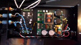
Here's a lousy cellphone pic of my GMARSH Wiener build.
First: thank you Gary for the turn-on/turn-off pop suppression circuit! On all my other tpa311x amps I had to wire up a "shutdown" switch. Now I can just use the power switch and not worry about it!
As you can see from the pic, I'm using an SMPS300RS from Connex Electronic. I had this one done in a custom voltage: 20v. There's a pot on the PSU that will let me change the voltage +/- 10%. There were a few subjective reports in the big tpa3116 thread suggesting that 21v (or was it 19v?) was the "best" voltage. I've got 19--21 covered!
The case came from China via eBay, with all the cut-outs pre-drilled (it says "Breeze Audio Mini Amplifier" on the front). Convenient, but the speaker binding post holes were too big for my usual red/black binding posts. So I used the big cheap-but-nice blue and green ones I got from Apex Jr. Now I just have to remember green=red and blue=black.
I'm waiting on a 50k stepped attenuator to use as volume control. That's why the cables from the RCAs to the amp's input are so long. They will eventually run to the front of the chassis to the pot, and another set of cables will run back to the input.
I'll also drill an additional hole in the chassis front panel for an LED.
The Bic mechanical pencil makes a nice dip-switch tool. I dropped the gain down to 20dB. Still running at stock switching frequency (1Mhz IIRC).
Using the highly precise touch my finger to the tpa3118 IC method of checking temperature, it's so far running cool. This is at moderate volumes in a nearfield setup, with Alpair 7.3 speakers. I added the thermal pad as per Gary's suggestion, and the chassis is downright cold to the touch, even right where the thermal pad touches the case. No surprises here, I suppose.
Sounds great so far! I haven't done any direct or A-B comparisons, just going from memory. But my gut impression is that the bass seems better with this amp than all my previous tpa311x builds. And by better, I mean more of it, and tighter/better defined. But that's a "shoot from the hip" comment, take it only with a salt mine.
Regarding the recent discussion above dealing with output filter values. I chose the 6ohm/TI recommended value, mostly in an attempt to be the jack-of-all-trades output filter. What do you folks think the "right" output filter is for the Alpair 7.3? The impedance curve's lowest point is around 6ohm at 300-400 Hz, and creeps up almost linearly (log-linear) to just over 10ohm at 20khz. Roughly 9ohms at 5khz, 8ohms at 2khz, 7ohms at 1khz.
Is there a potential for fatigue-inducing sound if this filter isn't done right?
First: thank you Gary for the turn-on/turn-off pop suppression circuit! On all my other tpa311x amps I had to wire up a "shutdown" switch. Now I can just use the power switch and not worry about it!
As you can see from the pic, I'm using an SMPS300RS from Connex Electronic. I had this one done in a custom voltage: 20v. There's a pot on the PSU that will let me change the voltage +/- 10%. There were a few subjective reports in the big tpa3116 thread suggesting that 21v (or was it 19v?) was the "best" voltage. I've got 19--21 covered!
The case came from China via eBay, with all the cut-outs pre-drilled (it says "Breeze Audio Mini Amplifier" on the front). Convenient, but the speaker binding post holes were too big for my usual red/black binding posts. So I used the big cheap-but-nice blue and green ones I got from Apex Jr. Now I just have to remember green=red and blue=black.
I'm waiting on a 50k stepped attenuator to use as volume control. That's why the cables from the RCAs to the amp's input are so long. They will eventually run to the front of the chassis to the pot, and another set of cables will run back to the input.
I'll also drill an additional hole in the chassis front panel for an LED.
The Bic mechanical pencil makes a nice dip-switch tool.
I dropped the gain down to 20dB. Still running at stock switching frequency (1Mhz IIRC).Using the highly precise touch my finger to the tpa3118 IC method of checking temperature, it's so far running cool. This is at moderate volumes in a nearfield setup, with Alpair 7.3 speakers. I added the thermal pad as per Gary's suggestion, and the chassis is downright cold to the touch, even right where the thermal pad touches the case. No surprises here, I suppose.
Sounds great so far! I haven't done any direct or A-B comparisons, just going from memory. But my gut impression is that the bass seems better with this amp than all my previous tpa311x builds. And by better, I mean more of it, and tighter/better defined. But that's a "shoot from the hip" comment, take it only with a salt mine.
Regarding the recent discussion above dealing with output filter values. I chose the 6ohm/TI recommended value, mostly in an attempt to be the jack-of-all-trades output filter. What do you folks think the "right" output filter is for the Alpair 7.3? The impedance curve's lowest point is around 6ohm at 300-400 Hz, and creeps up almost linearly (log-linear) to just over 10ohm at 20khz. Roughly 9ohms at 5khz, 8ohms at 2khz, 7ohms at 1khz.
Is there a potential for fatigue-inducing sound if this filter isn't done right?
Attachments
The output LC on the 4 ohm wiener is 10uH/1.5uF, which has a 41KHz resonant frequency. Unless your speakers look like a 2uF or bigger capacitor (I seriously doubt it) and effectively lower the corner frequency of the LC, it's not ringing you hear.
You might be hearing HF peaking, caused by your speakers being >4 ohms at high frequencies - what are you using for speakers?
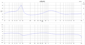
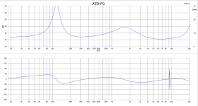
The speakers are my designs.. I'm running the 8ohm card only at the moment into one I call C4, impedance shown in first attachment.. I have a Realistic Minimus 7, second att, I'll try it out..
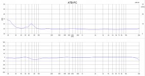
My 2.5way, in third att, I'll try 4 ohm with it later..
The C4 is small closed box monitor.. The amp sounds amazing, with a huge amount recorded space and detail exposed..
Have to study this later and see if I can solve what it is I'm hearing..
Attachments
Fun with reflow x2!
Spread the paste:
Stencil works great:
Placement of tiny parts still takes care:
Into the oven, one at a time to be safe:
Let the Arduino do the work:
Voila! This would have been outside my skills to hand solder:
BK
Spread the paste:
An externally hosted image should be here but it was not working when we last tested it.
Stencil works great:
An externally hosted image should be here but it was not working when we last tested it.
Placement of tiny parts still takes care:
An externally hosted image should be here but it was not working when we last tested it.
Into the oven, one at a time to be safe:
An externally hosted image should be here but it was not working when we last tested it.
Let the Arduino do the work:
An externally hosted image should be here but it was not working when we last tested it.
Voila! This would have been outside my skills to hand solder:
An externally hosted image should be here but it was not working when we last tested it.
BK
cool BK,
do you have a reference to the "Let the Arduino do the work:"
controller design/code? i have a toaster oven i can use.
Check out this link.
Credit to AMB, who pulled together bits and pieces for a prototype project I was a part of a while back - more details at his site under gamma 1.5.
BK
Gonna guess based on that plot.. Re is around 8 ohms, Le pushes the Z up to about 12 ohms at 20KHz, which means Zl is effectively 8.9 ohms at 20KHz, which works out to a Le around 70uH.The speakers are my designs.. I'm running the 8ohm card only at the moment into one I call C4, impedance shown in first attachment.. I have a Realistic Minimus 7, second att, I'll try it out..
My 2.5way, in third att, I'll try 4 ohm with it later..
The C4 is small closed box monitor.. The amp sounds amazing, with a huge amount recorded space and detail exposed..
Have to study this later and see if I can solve what it is I'm hearing..
Based on those #'s, throw a zobel on the speaker. R of 8-10 ohms, C around 1uF. This will pull the impedance back down towards 8 ohms at HF.
If my Octave install wasn't broken I'd calculate the amount of HF peaking based on the uncompensated speaker. I'll get that done soon enough.
Sorry, I did mention source and I am just not as smart as you are. Do enlighten me what TI is doing wrong to mislead me.So basically you don't know why, you're repeating something you read somewhere without understanding the underlying reasons, and without being certain that the statement is correct in the first place.
There's enough of that going on in the audio field already, please don't add to that
Attachments
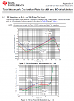
The SLOA119B Application Report and results therein you quote are based on a 250khz switching frequency. Change the switching frequency and you change everything else, most notably the effective load impedance which in turn change the optimal output inductor value as noted in SLOA119B.
If anything, smaller inductors would actually be preferable, in the sense that if you have 600khz-1mhz switching frequency you can easily set the filter frequency x1.5-x2 higher which in turn eliminates any possibility that the filter peaking will have any effect in the audible spectrum what-so-ever.
If anything, smaller inductors would actually be preferable, in the sense that if you have 600khz-1mhz switching frequency you can easily set the filter frequency x1.5-x2 higher which in turn eliminates any possibility that the filter peaking will have any effect in the audible spectrum what-so-ever.
Last edited:
Regarding switchingload, TI also answered designers that THD 3116EVM could be improved by increasing switching frequency, which seems to indicate same differences as results they posted for tpa3106EVM using higher switchingload in appnote. There is room for an increase to improve THD, just like in their appnote the 33uH outperforms the smaller inductors for THD. They also do point 3116/18 designers to this appnote.
That looks awesome!Fun with reflow x2!
Spread the paste:
(..snip)
I may actually give this a try for the round 2 group buy.
I'd take that plot with a grain of salt.Sorry, I did mention source and I am just not as smart as you are. Do enlighten me what TI is doing wrong to mislead me.
First of all, the Toko 11rhbp family has a really low current rating. Getting 20W into an 8 ohm load requires 2.5A RMS, or 3.5A peak with a sine source:
http://www.toko.co.jp/products/pdf/inductors/11rhbp.pdf
So they're pushing the inductors well past their "maybe they're not X uH anymore" rating. Different part values probably have a different winding count, winding AWG, air gap difference, possibly even material differences. Plus I can't find a L versus DC plot for this inductor family even at sensible currents. That difference in THD could entirely be caused by different characteristics of the inductors (other than the obvious uH difference).
Secondly, 33uH/1uF = 27.7KHz natural frequency, 22uH/0.68uF = 41.1KHz natural frequency - the frequency response of these two filters is going to be substantially different. With the 33uH inductor rolling off at a lower frequency, it's attenuating the harmonics more.
Harmonics are limited by AES17 (3rd harmonic for 6667hz is limit). You do see 33uH inductor distortion rising towards other two with higher watt, so yes the Ampères are visably affecting the 33uH more than the 22uH and 15uH.
Switchloadrise/uH difference vs lowered THD seems linear for first graph.
Switchloadrise/uH difference vs lowered THD seems linear for first graph.
- Home
- Group Buys
- "The Wiener" TPA3118 amplifier card