Yupp!
//
//
I think it would be interesting with an environment specification and some specific test cases where the DUT is exposed both mechanical and sound pressure which during the exposure, the phase noise is measured.
"Environmental Sensitivity
The MHM 2010 is designed to for low sensitivity to temperature, magnetic field and power supply changes."
.. they didn't say anything about mechanical resistance...
My idea was mostly to combat vibration from outside and specifically the acoustical one.
I suppose all the phase plots we see are in very quite and stable environment.
//
Vibration sensitivity for crystal oscillators: Vibration-Induced Phase Noise |
The magnitude of the vibration vs. phase noise vs. acoustic output would be the key question. if you have the phase noise setup working use the oscillator to a DAC and plat a 12 KHz tone (48K or 11.025KHz for 44.1K) (removes some other issues) and look at the sidebands at the output with a known SPL at the crystal. This is what you ultimately care about. The Phase noise is an intermediate product that translates into audio at some level. This is what you want to see. There are other microphonic things that can compromise your measurement so some effort to find and fix those is also important to getting the best from the system.
The magnitude of the vibration vs. phase noise vs. acoustic output would be the key question. if you have the phase noise setup working use the oscillator to a DAC and plat a 12 KHz tone (48K or 11.025KHz for 44.1K) (removes some other issues) and look at the sidebands at the output with a known SPL at the crystal. This is what you ultimately care about. The Phase noise is an intermediate product that translates into audio at some level. This is what you want to see. There are other microphonic things that can compromise your measurement so some effort to find and fix those is also important to getting the best from the system.
Place a small loudspeaker really close to the oscillator and play pink noise - observe phase noise spectrum?
//
//
Vibration sensitivity for crystal oscillators: Vibration-Induced Phase Noise |
The magnitude of the vibration vs. phase noise vs. acoustic output would be the key question. if you have the phase noise setup working use the oscillator to a DAC and plat a 12 KHz tone (48K or 11.025KHz for 44.1K) (removes some other issues) and look at the sidebands at the output with a known SPL at the crystal. This is what you ultimately care about. The Phase noise is an intermediate product that translates into audio at some level. This is what you want to see. There are other microphonic things that can compromise your measurement so some effort to find and fix those is also important to getting the best from the system.
Not too useful since you don't know what is what. If i had the setup here I would use a speaker measurement set to sweep a speaker near the DUT and use a reference mike close in to correct for the speaker response. They you could see everything including resonances, levels, phase response of the loop etc. My headphone test setup would be ideal. I use it for tuning ANC headphones. You would need a setup that supports the reference mike. ARTA may be able to do the same.
Hi,
Can anybody tell me whether this waveform coming out of my TWTMC-D AT looks normal?
This waveform is coming out of C5 just before the squarer.
driscollwave.jpg - Google Drive
After 24 hours of runtime and im still not sure its working properly, sounds like something is not right. I might try putting the cap trimmer on C1 and see if I can dial it in better.
Any comment appreciated.
Ryan
The scope has a major influence on what you see. However it looks like the oscillator is saturating on the negative limit. I thought there was an agc mechanism working in this oscillator.Hi,
Can anybody tell me whether this waveform coming out of my TWTMC-D AT looks normal?
This waveform is coming out of C5 just before the squarer.
driscollwave.jpg - Google Drive
After 24 hours of runtime and im still not sure its working properly, sounds like something is not right. I might try putting the cap trimmer on C1 and see if I can dial it in better.
Any comment appreciated.
Ryan
Hi,
Can anybody tell me whether this waveform coming out of my TWTMC-D AT looks normal?
This waveform is coming out of C5 just before the squarer.
driscollwave.jpg - Google Drive
After 24 hours of runtime and im still not sure its working properly, sounds like something is not right. I might try putting the cap trimmer on C1 and see if I can dial it in better.
Any comment appreciated.
Ryan
Keep in mind that if you are not using a fet probe you are loading the oscillator, so you don't see the real waveform.
Did you set R11 to get half Vo at Q1 collector (3V)?
If you are using a trimmer capacitor for C3 you could try to set if for the best waveform.
Otherwise you could increase the value of R2 or decrease the value of C2. In any case check for half Vo at Q1 collector after changes.
Hi wyan,
I can only answer from a somewhat general perspective as I would say that the actual choices depend on the setup. However, in any case I would place the "combined clock" as close to the DAC as sensibly possible with respect to EMR.
And, if you are designing the DAC yourself, if I remember correctly, then Henry Ott (signal integrity consultant) in his book stated that when routing a PCB the clock should be routed first (highest priority).
Yet if being specific I personally would not make longer wires between the oscillator and the squarer than what is needed for good isolation between the two circuit parts. As soon as the oscillator signal has been squared I consider it to be much more robust in terms of transmission over even slightly longer distances.
IMHO ;-)
Jesper
And one related question is if going separate box for master clock, is it better to send sinewave clock signal (put squarer circuit in dac box and some dac already has squarer built in) or to send square wave? Or it doesn't really matter? Thanks again.
I can only answer from a somewhat general perspective as I would say that the actual choices depend on the setup. However, in any case I would place the "combined clock" as close to the DAC as sensibly possible with respect to EMR.
And, if you are designing the DAC yourself, if I remember correctly, then Henry Ott (signal integrity consultant) in his book stated that when routing a PCB the clock should be routed first (highest priority).
Yet if being specific I personally would not make longer wires between the oscillator and the squarer than what is needed for good isolation between the two circuit parts. As soon as the oscillator signal has been squared I consider it to be much more robust in terms of transmission over even slightly longer distances.
IMHO ;-)
Jesper
temp measurements
hi everybody,
i just want to give an update on my recent tests regarding the twtmc.
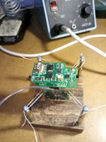
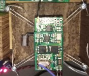
as reported before, isolating of the x-tal using rubber bands in a 4-point suspension revealed a more relaxed and natural sound , however, i found that the rubber bands lead to some kind of undesired resonance effects as well. to avoid that i got a tip from a friend to use tight "strings" instead of the rubber bands. so i replaced the rubber with "dental floss" (also a tip from a friend ;-) ) and the results ... wow!") very spatial and very detailed sound without any undesired resonance/oscillations !
very spatial and very detailed sound without any undesired resonance/oscillations !
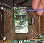
furthermore, i tested the influence of the oven temperature on the sound quality perception for 70°c - 100°c. the temperature was measured by a pt-100 probe and a dmm. i found this probe has advantages over the laser point infra-red, since the pt-100 has relatively small dimensions and you can almost scan the geometry at a resolution of 2mm x 2mm (or even less) whereas the ir-probe integrates the temperature over a bigger area and suffer from geometrical inaccuracy.
i measured the temperature at 2 points on the x-tal surface; one at the edge closed to the oven surface and one in the middle of the x-tal. the temperature at the edge is about 2°c higher than the middle of the surface. i assume that the temperature in the center of the x-tal (middel in the oven) should be few degree higher than on the surface.
results: the sound quality perceptions changes very clearly within the tested range. i want to claim that one would be able to hear even changes by few degree! i found the best temperature for my taste in my set-up at 89°c in the middle of the x-tal housing (91°c at the edge to the oven). i would describe difference in sound quality perception with increasing the temperature up to 89°c as follows: the sound gets somehow "richer" , the resolution gets better, especially for higher frequencies, and the overall performance gets more "livelier" and emotional. increasing the temperature over 91°c results in a bit harsh and less pleasant sound compared to 90°c.
again, the perception on the sound quality is not something "absolute" and can vary from person to person and from set-up to set-up! however, regardless how "good" an audio set-up is tuned to be, we know that every system has its weaknesses and by improving a certain part/unit of the set-up , other weaknesses of the system come more into the light because we bring the system out of balance! (this is why we improve and tweak endless to reach the perfect sound :-D ). imho, the balance/harmony of a system is primarily responsible for enjoying the music and not how perfect each unit "individualy" is tuned! sometimes it is even much better to use a less perfect unit as long as it masks the weaknesses of the rest of the set-up and delivers with it a more "balanced" performance. it means, if i enjoy the sound of my set-up at 90°c does not mean necessary that this is the best "working point" of the sc-cut xo. it just means that my system shows the best "harmony" at this temperature and the weaknesses of the set-up are less audible!
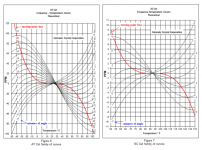
however, interesting is that the higher temperature around 90°c corresponds somehow more with the diagram of the sc-cut found in the forum. on my 45mhz x-tal it is labelled 81°c and my 49mhz has a 87°c label. maybe andrea can comment that and his recommendation for 82°c.
i would very much like to see if anyone else has already done similar tests and can share his/her findings and opinions?
best regards
hi everybody,
i just want to give an update on my recent tests regarding the twtmc.
as reported before, isolating of the x-tal using rubber bands in a 4-point suspension revealed a more relaxed and natural sound , however, i found that the rubber bands lead to some kind of undesired resonance effects as well. to avoid that i got a tip from a friend to use tight "strings" instead of the rubber bands. so i replaced the rubber with "dental floss" (also a tip from a friend ;-) ) and the results ... wow!
very spatial and very detailed sound without any undesired resonance/oscillations !furthermore, i tested the influence of the oven temperature on the sound quality perception for 70°c - 100°c. the temperature was measured by a pt-100 probe and a dmm. i found this probe has advantages over the laser point infra-red, since the pt-100 has relatively small dimensions and you can almost scan the geometry at a resolution of 2mm x 2mm (or even less) whereas the ir-probe integrates the temperature over a bigger area and suffer from geometrical inaccuracy.
i measured the temperature at 2 points on the x-tal surface; one at the edge closed to the oven surface and one in the middle of the x-tal. the temperature at the edge is about 2°c higher than the middle of the surface. i assume that the temperature in the center of the x-tal (middel in the oven) should be few degree higher than on the surface.
results: the sound quality perceptions changes very clearly within the tested range. i want to claim that one would be able to hear even changes by few degree! i found the best temperature for my taste in my set-up at 89°c in the middle of the x-tal housing (91°c at the edge to the oven). i would describe difference in sound quality perception with increasing the temperature up to 89°c as follows: the sound gets somehow "richer" , the resolution gets better, especially for higher frequencies, and the overall performance gets more "livelier" and emotional. increasing the temperature over 91°c results in a bit harsh and less pleasant sound compared to 90°c.
again, the perception on the sound quality is not something "absolute" and can vary from person to person and from set-up to set-up! however, regardless how "good" an audio set-up is tuned to be, we know that every system has its weaknesses and by improving a certain part/unit of the set-up , other weaknesses of the system come more into the light because we bring the system out of balance! (this is why we improve and tweak endless to reach the perfect sound :-D ). imho, the balance/harmony of a system is primarily responsible for enjoying the music and not how perfect each unit "individualy" is tuned! sometimes it is even much better to use a less perfect unit as long as it masks the weaknesses of the rest of the set-up and delivers with it a more "balanced" performance. it means, if i enjoy the sound of my set-up at 90°c does not mean necessary that this is the best "working point" of the sc-cut xo. it just means that my system shows the best "harmony" at this temperature and the weaknesses of the set-up are less audible!
however, interesting is that the higher temperature around 90°c corresponds somehow more with the diagram of the sc-cut found in the forum. on my 45mhz x-tal it is labelled 81°c and my 49mhz has a 87°c label. maybe andrea can comment that and his recommendation for 82°c.
i would very much like to see if anyone else has already done similar tests and can share his/her findings and opinions?
best regards
Attachments
@mr_whocares: Hi & thank you very much for sharing this ;-) ...
I have not yet myself tried out the effect of mechanically isolating the crystal but I will soon build a small block for the crystal (panzerholz, silicone, tungsten?) I use and then suspend it with wires/something else - along the lines of what you have done. I also remember seeing a picture of Herbert Rutger's setup while (I think) he was developing his oscillator ... He hung the crystal in thin curved bended wires above the PCB so that vibration from the PCB was absorbed by the curved wires ... Might be an EMR issue with e.g. 98 MHz crystals but IMO otherwise seems like a good idea in order to completely isolate the crystal itself.
Cheers, Jesper
Last edited:
mr_whocares, thank you for taking the time to share your findings with us. You might try to put the clock/oven PCB on a small piece of hard wood and then suspend the whole "assembly". This, supposedly, will further tame the low frequency micro-vibrations. I've heard some folks even add piece of lead for additional weight

- Status
- Not open for further replies.
- Home
- Source & Line
- Digital Line Level
- The Well Tempered Master Clock - Building a low phase noise/jitter crystal oscillator