Hi Jesper,
Nope, I wasn't able to find a stable 6V battery source for the XO part. The 6V battery could be 7V or more. The 3.3V rail is ok though. In fact, I prefer regulators. No need to take care of recharge issues.
Well, it seems that not many members talk about it. I've waited 2 years to complete the XO. The improvement of Andrea's work over NDK is hugh, IMHO. I feel the clarity got improved, too.
Hi Poting,
I'm glad you got good result with the XO, I got the same impressions when I compared the XO with the Crystek and other oscillators, more details, wider soundstage, realistic female voices.
Thank you for share your feedback.
I received a few e-mail from some members who got similar results, but they have not yet shared their impressions. I hope they will share their impressions with the audio community.
I think the reason of such that good results comes overall from the quality of the crystals. Laptech's stuff is very very good, maybe not the same quality of Croven or Bliley stuff, but not much different.
I'm planning to improve the Driscoll and the Pierce oscillators in the future... as soon as I find the time... now I'm spending my little free time working on a discrete DAC, it's a complex projects that will take long time.
I also work on another source of power,How to feed you the oven Canvas?
You have some photos
Acko Offers a special power supply for clocks,the AKR78X clock grade regulator,AckoDAC
Hi clsidxxl,
Well, this is it. It ain't pretty. The red ones are the LT3042 regulators. I got another 2 to power Ian's clock & PCM boards. From the spec, I bet Acko uses the same LDO.

Hi Poting,
I'm glad you got good result with the XO, I got the same impressions when I compared the XO with the Crystek and other oscillators, more details, wider soundstage, realistic female voices.
Thank you for share your feedback.
I received a few e-mail from some members who got similar results, but they have not yet shared their impressions. I hope they will share their impressions with the audio community.
I think the reason of such that good results comes overall from the quality of the crystals. Laptech's stuff is very very good, maybe not the same quality of Croven or Bliley stuff, but not much different.
I'm planning to improve the Driscoll and the Pierce oscillators in the future... as soon as I find the time... now I'm spending my little free time working on a discrete DAC, it's a complex projects that will take long time.
Hi Andrea,
Thanks for your efforts. Years ago, I ordered an SC-Cut OCXO from China. I have no means to test it, but it did change my view on XO. I'm sure the SC-Cut Driscoll with separate oven board shows more strength than before. The depth, clarity, top and bass all improved to certain degree over my previous NDK. Well, you can't beat NDK for its price. General speaking, it's still a nice XO for audio. Glad to hear your new R2R DAC project. I will wait for it for sure.
Poting
Hi clsidxxl,
Well, this is it. It ain't pretty. The red ones are the LT3042 regulators. I got another 2 to power Ian's clock & PCM boards. From the spec, I bet Acko uses the same LDO.
Hi Canvas
Thank you for the photos
") ,what do you use for feed the oven?
,what do you use for feed the oven?Hi Canvas
Thank you for the photos
The oven? It's fed from an unregulated power with separate winding. This power also serves the SPDIF interface board through Salas 1.2R regulator.
Poting
Thank Canvas,The pre-regulator of the LT 3042 is a Reflektor D ?
Yes, but these LT3042s are for Ian's boards. On the XO side, 2 LT3042s are powered from unregulated VCC which also supplies another Salas 1.2R regulator. I could use 1.2R as pre-regulator though. Will try that.
Hi Andrea,
I have a small problem with my clocks. I built a TWTMC A-I-O version using SC cut crystals for 45.15 respectively 49.15 MHz. For some reason, both channels start at much lower frequency, specifically 16.4 respectively 17.9 MHz. It looks like this could be the first harmonic of the crystals or a frequency that is very close to that. I tried a few things, but I can't make them run at the required frequency. Do you have any suggestions what I could try? I attached some photos of my boards below.
Thanks and regards,
Martin
Hi Andrea,
I have a small problem with my clocks. I built a TWTMC A-I-O version using SC cut crystals for 45.15 respectively 49.15 MHz. For some reason, both channels start at much lower frequency, specifically 16.4 respectively 17.9 MHz. It looks like this could be the first harmonic of the crystals or a frequency that is very close to that. I tried a few things, but I can't make them run at the required frequency. Do you have any suggestions what I could try? I attached some photos of my boards below.
Thanks and regards,
Martin
Hi,
what components value have you used for R1-R2-C1-C2-C3-L2 and L4?
Hi,
what components value have you used for R1-R2-C1-C2-C3-L2 and L4?
Taking a look at your pictures, seems L4 and L14 are missed, you have to install 18uH inductors.
Also, 6K8 for R11-R31 are suitable for 22/24 MHz AT-cut crystals, but for 45/49 MHz SC-cut you have to use at least 47K-56K, or better you should use a 100K trimmer to set half VCC (around 3V) at Q1/Q11 collectors.
Hello Andrea, the latest values that I have used were as specified in the table but I'll have to check that since I was trying different combinations. The indicator is there. I only had one in 1206 package since I made a mistake in my order, it didn't fit the pads and so I soldered it directly across the R and C. Good suggestion regarding the R11-R31, I'll try to get the 3V later today.Taking a look at your pictures, seems L4 and L14 are missed, you have to install 18uH inductors.
Also, 6K8 for R11-R31 are suitable for 22/24 MHz AT-cut crystals, but for 45/49 MHz SC-cut you have to use at least 47K-56K, or better you should use a 100K trimmer to set half VCC (around 3V) at Q1/Q11 collectors.
Regards, Martin
Hi Andrea,Hello Andrea, the latest values that I have used were as specified in the table but I'll have to check that since I was trying different combinations. The indicator is there. I only had one in 1206 package since I made a mistake in my order, it didn't fit the pads and so I soldered it directly across the R and C. Good suggestion regarding the R11-R31, I'll try to get the 3V later today.
Regards, Martin
I checked the components on the 49.15MHz channel and I found a few mistakes in values. What I have in now is: R1=680, R2=180, R11=75k, this combination gives 3V at C of Q1. Then I have C1=8.2p, C2=10p, C3=10p or NC, L4=1.5u and L2=22u (should be 18u but I don't have that one available). This improves things but now I'm getting 53.4MHz which is slightly too high. Any suggestion? Scope picture attached, measured with 500MHz 10:1 passive probe connected to the output.

Hi Andrea,
I checked the components on the 49.15MHz channel and I found a few mistakes in values. What I have in now is: R1=680, R2=180, R11=75k, this combination gives 3V at C of Q1. Then I have C1=8.2p, C2=10p, C3=10p or NC, L4=1.5u and L2=22u (should be 18u but I don't have that one available). This improves things but now I'm getting 53.4MHz which is slightly too high. Any suggestion? Scope picture attached, measured with 500MHz 10:1 passive probe connected to the output.
Seems with your values the oscillator starts at B-mode.
According to the TWTMC-D assembly guide, for an SC-Cut at 49.152 MHz the values should be:
C1=8.2pF
C2=2.2pF
C3=6.8pF
R1=1K
R2=330 ohm
L2=18uH (22uH is OK)
L4=1.2uH
So you have to change R1, R2, C2, C3 and L4 to their proper values.
OK, I had R1=1k and R2=330 originally but I couldn't get 3V at C of Q1 but only 2.4V I'll have to check my values tomorrow again.Seems with your values the oscillator starts at B-mode.
According to the TWTMC-D assembly guide, for an SC-Cut at 49.152 MHz the values should be:
C1=8.2pF
C2=2.2pF
C3=6.8pF
R1=1K
R2=330 ohm
L2=18uH (22uH is OK)
L4=1.2uH
So you have to change R1, R2, C2, C3 and L4 to their proper values.
Thanks
Hello Andrea,OK, I had R1=1k and R2=330 originally but I couldn't get 3V at C of Q1 but only 2.4V I'll have to check my values tomorrow again.
Thanks
I managed to make it work in the end. The combination that worked was: for 49.15MHz R1=680, R2=180, R11=75k, C1=8.2p, C2=2.2p, C3=6.8p, L2=22u, L4=1.2u. For 45.15MHz R1=680, R2=180, R11=75k, C1=8.2p, C2=2.2p, C3=6.8p, L2=22u, L4=1.5u.
There was a confusion because the document on TWTMC-D states different values in tables on pages 9-13 than in the table on the page 15. Like for example the value of C2 is 10p on page 6 but 2.2p on page 15 and this values seems to be quite critical. I measured the output using the scope again as well as the signal analyser and it looks very good. I need to put it into my system still and see what impact does this clock have on the sound.
Martin
An externally hosted image should be here but it was not working when we last tested it.
An externally hosted image should be here but it was not working when we last tested it.

An externally hosted image should be here but it was not working when we last tested it.
Last edited:
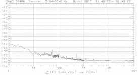
5.6448M SC-3, 11 dBm output.
-110 dBc@1Hz from the carrier is spectacular!
If I remember correctly the Q of the crystal is around 2M... the crystal quality makes the difference.
- Status
- Not open for further replies.
- Home
- Source & Line
- Digital Line Level
- The Well Tempered Master Clock - Building a low phase noise/jitter crystal oscillator