I try to take all precautions to avoid oscillation. Earlier, on the advice of Roar, I changed the value of the C6 / 7 to 100pF. Higher value is not recommended.
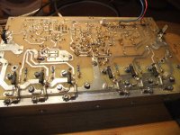
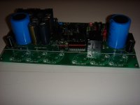
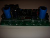
Today I made another change and followed up Jacco advice. Instead of using 10nF from each drain to common ground (C 20 - 26) I did what Hitachi recommend:Connected 1000 pF (1nF) from each drain directly to the heatsink. The cooling plate is also grounded directly to chassis ground at the phono input.
Now I will take a tentative period for changes in relation to the original clone. I will enjoy the results and the qualities that I think this amplifier have. A possible "come back" later with a recap of my listening experience.
Alex: Once again a wonderful job with a "new" print layout, BUT if this PCB is supposed to be "round two" with Golmund clone, listen to all the experiences that have so far been done, and which completely resolved improves clone compared to the original. There is plenty of room for an improved power supply for the front end on your excellent print, if you replace all the components now used to the "hopeless" voltage doubler
Eivind Stillingen
Attachments
new to these forums so beg forgivness if I miss the finer points or intended purpose. this thread is about the "Goldmun memisis" amp? which is basically the hitachi MOSFET app circuit in reverse polarity with mods to front end ie a constant current source in the long tail pair plus some J-fets? use a similar arrangement myself just not inverted with an extra driver pair to take care of charge/discharge of mos gates works well but have to run close to the limit heatwise on the driver card got a 5w carbon resistor 10k/(bypass cap) but sounds very "Valve" lately using just 2 mos devices as drivers to drive comp BJT's as outputs similar to "Adyton" kit from 80's I digress what is the wonder with this well known topology of hitachi???
I digress, what is the wonder with this well-known topology of Hitachi ?
The attention to details ?
There's Spectral DMA100, Perreaux 1050, or a Maplin assembly kit.
(Andy_C and Bruno Putzeys write interesting lines on ocassion)
The attention to details ?
There's Spectral DMA100, Perreaux 1050, or a Maplin assembly kit.
(Andy_C and Bruno Putzeys write interesting lines on ocassion)
Oh this is a quest for the diminishing returns exercise? attention to details?? surely do that anyway.. always pay attention... hhmmm "Maplin" the "hitachi" app circuit so its about getting this application notes circuit to function well??? coz been there done that..just run the driver circuit hot (high bias) a quick mod on the old BK modules I used to sell for commercial purpose my bench Eng at that time did it made him curious to study some more.its a good topology runs class A been badly used a lot though. expectations of sometimes small signal BJT's expected to handle banks of Mosfets!
ignorance showing again... are these devices discussed here used for home audio? or pro-audio? been in both sides of those industries. but all this forum thing is not gelling for me yet but if it about education I am all for it.
do not work in it now just electronic things for a bit of a diversion nowadays
Anyone got an "Adyton" "HY358A Hybrid" be great help fix an amp got here

I have today completed what I described in # 1504 ....
1. T3 / 4 was replaced with matched BC546 B. The result was exactly the same as with matched MPSA 42: A unstable DC at the output, but DC still remains well within a secure margins. Conclusion: It is hip happening what transistors used for T3/4 with respect to stable DC levels.
2. C20 to 26 (10 nF) between the drain and common ground was replaced with 1 nF between every drains and the heatsink as Hitachi suggest (see #1174). In addition, the heatsink was attached to the chassis GND at the phono input.
First I thought I had done something wrong when I connected one speaker:
The sound of a snake got me quickly to turn variotransformer down. But when the result was exactly the same with the other speaker, I quickly concluded that what I heard, was due to the changes I had done likely in both channels. Out with 1 nF from drain to the heatsinks and back with 10 nF, as it was originally. Gone was the noise/snake.
Why Hitachi's recommendation led to increased noise, I have no explanation. But on my Golmund clone, the result was not what I expected.
I see no reason that such a change would fall out fortunate for others that use Alexs print layout, and I would not recommend trying this solution.
Eivind Stillingen
Dadod
In # 1174 I asked for comment on what to do with C20-26 if a 1 nF was used fom drain to heatsink.
Jacco answered me, and there were also other comments on this subject (#1458/9)
In #1470 Jacco wrote: The link was Not meant to add more confusion, Not implying that you should exchange the 10nF for 1nF, or use both (pfff).
I would appreciate to get more comments on this subject before I do a second try mounting both 10 nF and 1 nF.
Eivind Stillingen
NOT implying that you should exchange the 10nF for 1nF
And still you did, right ?
More important question you should ask yourself : What's alive on that heatsink that turns your amp into a snake !
Jacco
You wrote:
And still you did, right ?
In your opinion, did I?????
Or should I listen to Dadods adwise???
Sorry, but here I need adwise, not question!!
You wrote:
More important question you should ask yourself : What's alive on that heatsink that turns your amp into a snake !
Again, I do not have any idea or any experience of "Whats alive on the heatsink"
Can you please be more precise and tell me what you think is on my heatsinks?
Eivind Stillingen
You wrote:
And still you did, right ?
In your opinion, did I?????
Or should I listen to Dadods adwise???
Sorry, but here I need adwise, not question!!
You wrote:
More important question you should ask yourself : What's alive on that heatsink that turns your amp into a snake !
Again, I do not have any idea or any experience of "Whats alive on the heatsink"
Can you please be more precise and tell me what you think is on my heatsinks?
Eivind Stillingen
http://en.wikipedia.org/wiki/Rhetorical_question
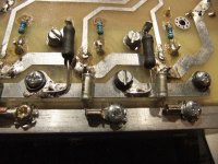
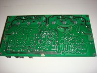
To tell the truth, just the view of the bottom of your boards makes my toes curl.
The Memisis is like an F1 racing car :very fast and no ABS, ESC, ESP, TCS, no Airbags, no crumple zones.
Such a car needs an F1 mechanic to assemble it.
Someone with two weeks experience at a tire-center can ask directions at any stage beyond a wheel exchange.
But without books/nightschool classes, any response leads to more confusion, more questions, and fewer answers.
Example is switching the BSS71/74 drivers for MJE340/350.
An MJE350 does an fT of 4 Mhz, 8 if you're lucky, measured at an Ic of 50-100mA
fT is : current gain-bandwidth product.
Basically means they measure what frequency a transistor is able to do at each collector current, and how high Hfe is.
fT is the product of : gain times frequency.
The Goldmund has a risetime in the order of 0.5 µs , with a bandwidth of well over 100KHz at -0.1dB and close to 1MHz at -3dB.
If you looked at the numbers (aka graphs in the datasheets) , the BSS71 and BSS74 ARE able to deliver that.
At less than 2mA driver current, the MJE350 NOT by a long shot.
Quoting you : you do not have any idea.
Unfortunately, you also do not seem to grasp what i post.
Maybe others can help you out.
Hi,
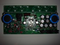
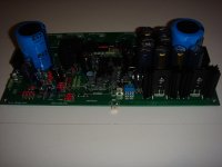
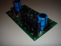
I'm close to finish! I have to solder a few components, followed by the mounting of lateral mosfets. I have great emotions and I'm eager to listen to this amplifier!
See you soon
I'm close to finish! I have to solder a few components, followed by the mounting of lateral mosfets. I have great emotions and I'm eager to listen to this amplifier!
See you soon
Attachments
Say, you didn't want the shabby and overpriced boards from bigpanda?
Why you throw every time oil on the fire in the thread of the Goldmund clone
Looks good.
Where do you have the board with soldermask from?
Say, you didn't want the shabby and overpriced boards from bigpanda?
if you did not buy the board, keep your complaining to yourself......we are trying to move on here....do something usefull....
Why you throw every time oil on the fire in the thread of the Goldmund clone
Because I'm an evil person.
(But everybody knew this anyway.)
I find it fascinating that hotzman has soldermask covered boards and I'm curious what he paid for them. I find they look much better than the tinned ones.
No, I won't start again with what caused a lot of excitement before. The thing is over and the winner is... - you figure it out yourself.
(Hint: It's not me and it depends on you whether you will succeed getting the "best amplifier in the world on the best circuit boards ever made" stable.)
Sorry for my needling. Just don't take it too serious, ok?
- Home
- Amplifiers
- Solid State
- The Very Best Amplifier I Have Ever Heard!!!!