$1 Million Price
Switzerland, duh, a million dollares stereo i can order at 5 miles around the corner of my place of burb.
http://www.kharma.com/_images/downloads/hq_images/Speakers/Grand Enigma System/grengr.jpg
(The Sovereign tower amps even sucket when i heard them 20 years ago. Siltech stopped the fancy pants amps, but you can still get solid gold chopsticks from them)
Last edited:
I think just the stereo is $1M in the reception room, the HT room must be some $xM. The cabinet contours and flush mounting for diffraction control and the exotic drivers are awesome though. You need such impulse coherence to appreciate a company's amps that their design hallmark is reproduction of realistic time as highlighted in their seminar.
Attachments
I like the suggestions to post a photo or scan of the EXACT schematic for the proposed amp. This is going to cost at least 500.00 and that is a tidy sum to many.
A nice accurate layout is important.
I also think that an increase of 25-30 percent for SOAR in plastic to-247 devices is not asking too much. Three pairs of metal cans equals 4 pairs of plastic.
Tad
I am about 80% done laying out the schematic in KiCad, IF anyone is ahead of me please save me some time and trouble. I have not added the protection circuit YET.
I will post it with in a day or two. I will add and insert what I feel is prudent to the circuit and topology. I don't know much, but will try to contribute what I have learned building amps in the past 40 years. I will make available the KiCad schematic so that others way smarter than me can sprinkle their own magic dust on it and we can all share in the huge knowledge base gazing upon the design.
Thanks to all for input and comments.
I figured it out I saved it as a PLOT to the clip board then opened Paint as you suggested and pasted it in and save that as a jpg.
Thanks
Here it is....
It is NOT done, so no spitballs yet...
I also had to shrink it to fit the JPG criteria...
Thanks
Here it is....
It is NOT done, so no spitballs yet...
I also had to shrink it to fit the JPG criteria...
Attachments
Last edited:
Hi
These is a another Goldmund design. I would be interested on these to .
All I know these is the mono block , newer version.
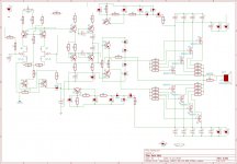
Any opinion on these schematic??
Unfortunately these PC board to complex to me ....
Some picture and the schematic..
Greets
Gabor
These is a another Goldmund design. I would be interested on these to .
All I know these is the mono block , newer version.
Any opinion on these schematic??
Unfortunately these PC board to complex to me ....
Some picture and the schematic..
Greets
Gabor
Attachments
gaborbela - Can I ask you where you got the schematic from? This looks partially like their late 90s early 00s JOB based circuit amplifiers mixed with Mimesis input stage. I will double check and get back. From the looks of it, I will say this is a fake NOT Goldmund schematic. Some sort of a clone/copy, but from someone who did not have the JOB's input stage schematic, so they used A1 block from Mimesis instead. Probably using the A1's schematic from my previous posts on the internet.
These only use 2 pairs per channel
There are no power mosfet at the bottom , it has option to use 4 pairs but it was built only with two pairs.
I would be interested to get a pair PC boars like these
Greetings Gabor
There are no power mosfet at the bottom , it has option to use 4 pairs but it was built only with two pairs.
I would be interested to get a pair PC boars like these
Greetings Gabor
Attachments
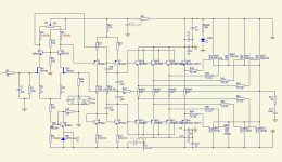
These 100% Goldmund mono block!
I sow the picture from the orig Goldmund , the guy opened up an made some picture from it , at firs it was hard to believe to me to .
After I sow the picture I'm sure these orig Goldmund!
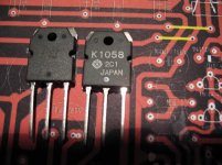
I wanted to buy PC boards but the guy sell kits only .I don't want any Renesans lateral I have orig Japanese Hitachi !
So that reason I didn't get a kit..
Hi,
I sold because I need to order him again with bigger model
He also have 600WRMS model with balanced input but too expensive.
Mosfets : hitachi
Jfets : vishay
Resistors : vishay draloric
smd capacitors : panasonic
filter capacitors : philips
PCB : Glass Epoxy FR-4
All parts as same as Goldmund!!!!!
That PC board use 4 pairs mosfet per channel and Philips axial capacitors !
Greetings
I sow the picture from the orig Goldmund , the guy opened up an made some picture from it , at firs it was hard to believe to me to .
After I sow the picture I'm sure these orig Goldmund!
I wanted to buy PC boards but the guy sell kits only .I don't want any Renesans lateral I have orig Japanese Hitachi !
So that reason I didn't get a kit..
Hi,
I sold because I need to order him again with bigger model
He also have 600WRMS model with balanced input but too expensive.
Mosfets : hitachi
Jfets : vishay
Resistors : vishay draloric
smd capacitors : panasonic
filter capacitors : philips
PCB : Glass Epoxy FR-4
All parts as same as Goldmund!!!!!
That PC board use 4 pairs mosfet per channel and Philips axial capacitors !
Greetings
Last edited:
The pictures you posted are NOT Goldmund, they are fake clones, 100%. Trust me on this one. I've repaired, owned, and sold more Goldmund equipment than I can count. The schematic is also pieced together from 2 different generations of Goldmund amps. I would not build this schematic.
My schematic is the only true Goldmund schematic on the entire internet. It was hand drawn from an ORIGINAL Goldmund schematic that came directly from them.
These Chinese clones on eBay are terrible. It's from people who have bits and pieces. Beware and stay away, what a mess.
My schematic is the only true Goldmund schematic on the entire internet. It was hand drawn from an ORIGINAL Goldmund schematic that came directly from them.
These Chinese clones on eBay are terrible. It's from people who have bits and pieces. Beware and stay away, what a mess.
Hello
These two different amp from two different source!
The amp which uses 4 pairs mosfet that is a new Goldmund clone , that is 100%.
I sow the picture of the orig Goldmund .
I would not care about at all , not for a minute.
Another clone which use 2 pair mosfet I'm not sure! Even the guy who sent me picture from the orig Goldmund (amplifier , orig stuffed PC board , protected transformer with the sign Goldmund) He wrote that not orig (with the brown caps)
I sow those pictures, believe me .(Unfortunately I didn't kept them after he didn't sold kit with out the Renesans mosfet!!)
But please look after, may be you can find more info..
Probaly the guy who sell the Goldmund kit does not want to another people clone it again so he left out something from the schematic.
I believe because I sow it! Only problem the orig use double sided PC board and I didn't sow the bottom!
These is a new Goldmund clone , over 300K price !!!
I'm also interested on yours because more info , PC board etc.
Greets Gabor
Last edited:
this is the only time I have seen a design where the outputs have significantly higher voltage rails than the frontend or VAS.
Tad,
how much is the difference then ?
Basic wet pinky rule : total Pd is 3 times continuous power, minimum.
Lateral MOSFETs do not suffer from second breakdown, but continuous thermal overload does terminate them.
For a 250 watt amp that means 4 pairs (8 times 100W)
Use less output devices => buy fans, big ones.
Examples : Perreaux PMF5150/5550 (aka big fan-fans)
Power Supply 101 :
-AC mains voltage is allowed to go up 10%
-Transformer regulation is roughly 5%
Means +/- 60Vdc nominal rails can go up to +/- 70Vdc for Class AB amps.
Make a Class AB amp do +100KHz : 140V devices go to Swiss heaven during fast transients if the rails go higher than 70Vdc.
BJT or MOSFET makes no difference.
(if the Bocca del Oro company so smart, why use SNOB5 circuits ?)
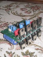
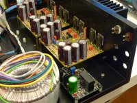
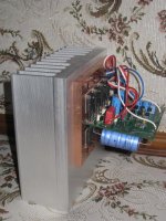
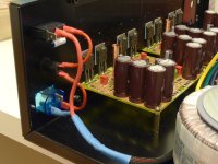
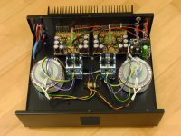
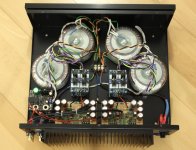
Here is some parts of communication between me and the Goldmund kit seller
http://www.diyaudio.com/forums/swap-meet/170360-fs-hi-end-chassis-gm-symasym-gain-clone.html
After we exchanged e-mail address and he sent pictures from the orig Goldmund!
Only problem he did not sell kit with out power mosfet. I hate the Renesans mosfets, I com pared them with the orig Hitachi. Huge difference soundwise!
I have 15 pairs orig Hitachi why should I buy those Renesans I do not like them.
Greetings
Attachments
Here is some parts of communication between me and the Goldmund kit seller
http://www.diyaudio.com/forums/swap-meet/170360-fs-hi-end-chassis-gm-symasym-gain-clone.html
After we exchanged e-mail address and he sent pictures from the orig Goldmund!
Only problem he did not sell kit with out power mosfet. I hate the Renesans mosfets, I com pared them with the orig Hitachi. Huge difference soundwise!
I have 15 pairs orig Hitachi why should I buy those Renesans I do not like them.
Greetings
How do you know he is telling the truth and this is the real thing?
Tad,
how much is the difference then ?
Basic wet pinky rule : total Pd is 3 times continuous power, minimum.
Lateral MOSFETs do not suffer from second breakdown, but continuous thermal overload does terminate them.
For a 250 watt amp that means 4 pairs (8 times 100W)
Use less output devices => buy fans, big ones.
Examples : Perreaux PMF5150/5550 (aka big fan-fans)
Power Supply 101 :
-AC mains voltage is allowed to go up 10%
-Transformer regulation is roughly 5%
Means +/- 60Vdc nominal rails can go up to +/- 70Vdc for Class AB amps.
Make a Class AB amp do +100KHz : 140V devices go to Swiss heaven during fast transients if the rails go higher than 70Vdc.
BJT or MOSFET makes no difference.
(if the Bocca del Oro company so smart, why use SNOB5 circuits ?)
Hi Jacco,
I didnt think the pmf550 had a fan, heres some pics, these were pretty cool in the day.
Massive 5150B gets a brother - AudioKarma.org Home Audio Stereo Discussion Forums
- Home
- Amplifiers
- Solid State
- The Very Best Amplifier I Have Ever Heard!!!!