I've been thinking about what exactly would happen if I properly stuffed all 16 of my horn subs into a cargo trailer and cranked it up to 11 ???
Specifically, I was curious about doing a v-plated cardioid array, with two rows of subs inside of the trailer, but I am trying to figure out the sound physics a little better first, so please enlighten me if you understand how that all would work.
I use a cargo trailer to transport my gear to event venues. But I also do outdoor events, private parties, and work in bad weather - so I thought that it would be interesting if I could run all subs from inside the trailer without unloading it - turning the entire trailer into an "extended horn" of sorts - I modeled several stacking arrangements (could post a pic), none of which look reasonable, except for maybe this cardioid setup.
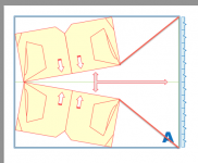
The idea is to stack the subs 4-tall, 2-wide mouth-to-mouth, in a V-Plate arrangement. That would be half of subs. Then, put the second half of subs in a cardioid row firing in the same direction, but a quarter wavelength behind the first row. In theory, the two wavefronts should combine in the direction they are firing, also doing some phase cancelation in the rear direction.
I'm curious about what factors I am not considering. Standing waves. Reflections. Choking. Unintended phase cancelation.
Opinions? Ideas for improvement? Or maybe just a good psychiatrist recommendation? : )
INFO:
- trailer dimensions: 20'L x 8.5'W x 10'H
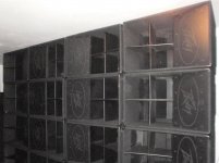
- 16x Peavey SPFH "E-horns" that are similar in design to old Cerwin Vegas (36''x36''x24'') - 800 wRMS each - powered by four Macrotech 9000i @ 2 cabs per channel.
- DBX Driverack VENU360 processor and other DSPs available.
- I also have a full poly line array powered by XTI-4002s' that could easily be deployed to the sides of the trailer.
Specifically, I was curious about doing a v-plated cardioid array, with two rows of subs inside of the trailer, but I am trying to figure out the sound physics a little better first, so please enlighten me if you understand how that all would work.
I use a cargo trailer to transport my gear to event venues. But I also do outdoor events, private parties, and work in bad weather - so I thought that it would be interesting if I could run all subs from inside the trailer without unloading it - turning the entire trailer into an "extended horn" of sorts - I modeled several stacking arrangements (could post a pic), none of which look reasonable, except for maybe this cardioid setup.
The idea is to stack the subs 4-tall, 2-wide mouth-to-mouth, in a V-Plate arrangement. That would be half of subs. Then, put the second half of subs in a cardioid row firing in the same direction, but a quarter wavelength behind the first row. In theory, the two wavefronts should combine in the direction they are firing, also doing some phase cancelation in the rear direction.
I'm curious about what factors I am not considering. Standing waves. Reflections. Choking. Unintended phase cancelation.
Opinions? Ideas for improvement? Or maybe just a good psychiatrist recommendation? : )
INFO:
- trailer dimensions: 20'L x 8.5'W x 10'H
- 16x Peavey SPFH "E-horns" that are similar in design to old Cerwin Vegas (36''x36''x24'') - 800 wRMS each - powered by four Macrotech 9000i @ 2 cabs per channel.
- DBX Driverack VENU360 processor and other DSPs available.
- I also have a full poly line array powered by XTI-4002s' that could easily be deployed to the sides of the trailer.
A bit of inspiration for you.
https://youtu.be/o36Kp6veJ6c
THE MATTERHORN | Danley Sound Labs, Inc.
Tom Danley is a forum member and a real nice guy.
https://youtu.be/o36Kp6veJ6c
THE MATTERHORN | Danley Sound Labs, Inc.
Tom Danley is a forum member and a real nice guy.
Matterhorn is certainly an inspiration and something that I've looked at before. I am well aware of Mr. Danley's talents and considered building LABsub's before I ended up with my E-horns. Bill Fitzmaurice and his forum has also been a source of great information.
The goal right now is to figure out how to re-purpose my existing speakers for "secondary" use without the hassle of unloading and setting up.
I am looking for someone with a better understanding of sound physics than me to chime in about how well this idea would work.
The goal right now is to figure out how to re-purpose my existing speakers for "secondary" use without the hassle of unloading and setting up.
I am looking for someone with a better understanding of sound physics than me to chime in about how well this idea would work.
In a small enclosed space your cardioid models won't apply due to the various reflections from inside the trailer being out of phase from the frontal output.I
The idea is to stack the subs 4-tall, 2-wide mouth-to-mouth, in a V-Plate arrangement. That would be half of subs. Then, put the second half of subs in a cardioid row firing in the same direction, but a quarter wavelength behind the first row. In theory, the two wavefronts should combine in the direction they are firing, also doing some phase cancelation in the rear direction.
I'm curious about what factors I am not considering. Standing waves. Reflections. Choking. Unintended phase cancelation.
Opinions? Ideas for improvement? Or maybe just a good psychiatrist recommendation? : )
INFO:
- trailer dimensions: 20'L x 8.5'W x 10'H
Not to mention with half the sub energy inside the trailer, it would rattle like a dumpster dropped down the side of a mountain...
That said, if you deployed the subs in a 12" wide by 8" high cluster (higher and more narrow would be better if possible with the frontal dimensions) with an opening on one side of the 20' trailer, the remaining 4"x10" "barn door" on either side would result in at least 3 dB forward gain, like doubling your amplification without any thermal limiting.
You would have to make sure the load weight was balanced left to right and secured for safety when traveling.
Art
I usually deploy the subs at venues as one 24'-long front row, 2 cabs tall, 4 clusters, one next to each other, stacked mouth to mouth. I've thought about different stacking arrangements inside of the trailer. Manufacturing is not a problem, really, but I'd rather not modify the trailer too much. Opening one side of the trailer was one of the options that I have considered - and one-sided weight is what made me write that idea off - I'd like to not have to reposition the cabs inside the trailer after transporting. I've also thought about opening two opposing sides and using folding extensions to create sides of horn. I'd prefer not to cut the trailer though, if at all possible, but it's an idea.
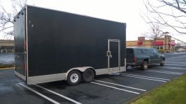
I've considered using a box truck that has one side open, like curtain trucks, or beverage delivery. But then the subs would be 2-4 feet above the ground and we all know what happens at that height. I then thought about getting a lowboy trailer with a shipping container that would not "flex" like an aluminum trailer. But I would prefer to use the existing trailer and do as little mods as possible. Insides could be reinforced with some Baltic Birch to prevent rattling. Trailer is rated at 12K lbs and full system weights 8K with amps.
I am attaching a PDF with a few options that I've thought about and wrote-off as a no-go. Figure "C" shows the alternative with openings on both sides and foldable "horn extensions". Note about diagrams - due to space - had to "show" just half the trailer (10ft long in pix)... If I could figure out how to keep the trailer without cutting, that would be best, but I'm also open to all other ideas...
And maybe I am just crazy and none of it is possible...
But maybe something new could materialize from this discussion...
Attachments
Having subs 2-4 feet above ground level makes virtually no difference in response compared to on the ground in the forward plane, though will result in a response dip in the vertical plane- birds will hear slightly less output when flying directly above.I've considered using a box truck that has one side open, like curtain trucks, or beverage delivery. But then the subs would be 2-4 feet above the ground and we all know what happens at that height.
I am attaching a PDF with a few options that I've thought about and wrote-off as a no-go. Figure "C" shows the alternative with openings on both sides and foldable "horn extensions". Note about diagrams - due to space - had to "show" just half the trailer (10ft long in pix)... If I could figure out how to keep the trailer without cutting, that would be best, but I'm also open to all other ideas...
I have modified your diagram showing horn extenders in red, which would work OK, and require no (permanent) trailer modification. Delaying the forward cabinets by around 3ms should improve coherency and would increase forward directivity a bit. I'd expect the low corner to drop from around 47 Hz to close to 30 Hz.
Art
Attachments
oh, that's very interesting, horn extenders inside!
thank you for toying with my idea, Art, that tells me that I have not yet gone totally crazy and at least "something" could be done to set up the trailer with sub arrays like I envision... I realize that there are always some drawbacks and something going to have to give somewhere... but it would be interesting to experiment with and see how good of an alternative this is...
if we keep playing with design "A" for now (still being open to other ideas)... I'm targeting recorded and dj dance music frequencies... one question would be about the optimal distance to the drop-down door from the stacks (and from which point of the stacks)... also how, or if, the back chamber would affect the performance... I don't mind building an extra wall to try and contain the rear chamber more if needed... but I also don't mind putting them against the back wall and having very long "horn extenders"... I'm sure there's much more science behind it and this distance could be calculated... I am still trying to find a way to fully wrap my mind around sound wave physics and phasing (especially 3D) and could use some suggestions")
thank you for toying with my idea, Art, that tells me that I have not yet gone totally crazy and at least "something" could be done to set up the trailer with sub arrays like I envision... I realize that there are always some drawbacks and something going to have to give somewhere... but it would be interesting to experiment with and see how good of an alternative this is...
if we keep playing with design "A" for now (still being open to other ideas)... I'm targeting recorded and dj dance music frequencies... one question would be about the optimal distance to the drop-down door from the stacks (and from which point of the stacks)... also how, or if, the back chamber would affect the performance... I don't mind building an extra wall to try and contain the rear chamber more if needed... but I also don't mind putting them against the back wall and having very long "horn extenders"... I'm sure there's much more science behind it and this distance could be calculated... I am still trying to find a way to fully wrap my mind around sound wave physics and phasing (especially 3D) and could use some suggestions
Attachments
By "rear chamber" you seem to be talking about the space behind (in front of the trailer) the speaker cabinets, as opposed to the compression chamber in each enclosure, AKA "rear chamber". If the cabinets do not create an adequate seal between the trailer sides, a wall should be used.one question would be about the optimal distance to the drop-down door from the stacks (and from which point of the stacks)... also how, or if, the back chamber would affect the performance... I don't mind building an extra wall to try and contain the rear chamber more if needed... but I also don't mind putting them against the back wall and having very long "horn extenders"... I'm sure there's much more science behind it and this distance could be calculated... I am still trying to find a way to fully wrap my mind around sound wave physics and phasing (especially 3D) and could use some suggestions
The enclosed spaces behind the horn extenders could be accessed with gasketed doors.
Using the free Hornresp simulation program you could compare the effect of longer and shorter horn extensions. The use of a parabolic extension on the end of a roughly hypex horn is not optimal, but you should be able to get an idea of what it will do, and by doing the modeling will start to get a handle on the various aspects of the physics involved.
Have fun, good luck!
Art
Yes, I did not mean an acoustical rear chamber, just the space that would be left behind the stacks, in the front of the trailer. That area actually already has a front access door anyway. Sounds like building a wall to separate it would make sense.
I've not played much with hornresp in years, I hear it's been updated lately, not sure yet how exactly I would enter the parameters of my "stacks" as "drivers" for the horn model, but I'm sure it can be done, I will play with it and post questions when I formulate them.
One question related to sound physics - what will be the effects of the array "A" discussed above being splayed at only about 20 degrees between stacks - how will the sound waves combine in the small space between the stacks and proceed in the direction of the horn extenders? I'm sure there is some science behind that as I've seen similar style cabs built with two drivers inside almost facing each other. I am assuming that bass stacks will couple and function essentially as two large single wavefronts combining together inside of the 20-degree V...
The easiest way to find out is to stack it up, put a pair of 4x8" waveguides up with one on top and measure outside, then compare it to the same flat front stack. The "waveguide" may or may not have much impact on the low corner, or output, but at least will get the center of balance closer to the trailer axlesOne question related to sound physics - what will be the effects of the array "A" discussed above being splayed at only about 20 degrees between stacks - how will the sound waves combine in the small space between the stacks and proceed in the direction of the horn extenders?
.It may actually be a better idea to simply line the subs on either side of the trailer, rather than "V" them, "tunnel end fire", again with front subs delayed by the mouth center to center distance. This would also require a seperation wall, but the "V" plates could be eliminated.
Another interesting idea! So, an option would be to line sub stacks against two opposing walls and fire them towards the center, with a sturdy separator in between? Is that separator (going down the center free line in the diagram) same as the "waveguide" proposed for the V array? Wouldn't such a separator in a V cut the angle down to just about 10 degrees? For some reason it seems like stacking them in a V is a more logical extension of a horn. I am currently on the road hauling the empty trailer home so that I can start measuring it and photo of it is attached.
Attachments
1) No separator between the stacks, just stacks as in diagram "A", with the left side top and bottom brought flush to the trailer walls. The "V" "barn doors would probably do little compared to the 90 degree cabinet edges at low frequencies, but might clean things up a bit in the 100+ Hz region.1)Another interesting idea! So, an option would be to line sub stacks against two opposing walls and fire them towards the center, with a sturdy separator in between?
2)For some reason it seems like stacking them in a V is a more logical extension of a horn.
2) A "V" seems like a logical horn extension, but your horn mouths have already expanded, the reduced cross sectional area in the "V" section starts a secondary (shorter) horn over again.
I revise my initial suggestion that the "V" would drop the low corner
.To actually optimize response for the trailer would require a new horn design.
That said, flown "tunnel end fire" (cones facing each other, front units delayed from rear) have been effectively used on several arena tours, there is some light the end of the tunnel
. Art
Got home late last night and did not get to measure the exact trailer dimensions yet. Still trying to determine the best cab stacking option of course. Re-read again previous posts and have more questions now : )
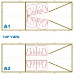
Based on my first diagram, options B, C, and D do not seem to be practical and are eliminated for now. The remaining option (A) could be deployed either as (A1) two stacks in a V pattern or (A2) as two stacks in a tunnel-fire pattern. Main difficulty with making A2 "completely flush" against walls is that I will have to leave space in the rear of cabs to plug wires.
I've updated the picture to show the length of the entire trailer rather than just half as in first set of pix. I've included options A1 and A2, with the "extensions" remaining the same length on the diagram for comparison purposes. Sounds like extensions would not even be necessary with option A2 - if that's what the following comment meant - "the "V" barn doors would probably do little compared to the 90 degree cabinet edges at low frequencies" ???
I am also not quite clear about what exactly was the "waveguide" mentioned in this case? I am guessing the waveguides would be (1) the rear door of the trailer dropped to the ground, and (2) an extra flap made to swing up??? Or are we talking about horn extenders inside? Or something entirely different?
Interesting point about the horn mouth's of the cabinets being "already expanded" by the cabinet design... However, these are not true "folded" horns, they are more like "E" horns, which I understand are not long enough to be called a "real folded horn", so would that make things different? Are these "E" horns also considered fully expanded at the mouth? How is the general physics of using a "cabinet" different from physics of using a "driver" to create the initial source of sound inside of a bass horn?
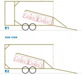
I came up with yet another option today (E). Instead of looking at the trailer from the top view, I looked at it from side view, creating a different horn. I remember reading up about boundary reinforcement and BFM suggesting that if no boundary is available, tilting the cabs forward against ground would create a horn extension of sorts (although, aren't BMF Tubas fully expanded at mouth, too?). Drawbacks to using E1 and E2 designs would be a significant lack of storage space for anything else in the trailer and the difficulty with loading and unloading at indoor venues. I included options E1 and E2 just to show them off. And a blank template in case if anyone wanted to move shapes around.
Any additional input, opinions, or theory explanations are greatly welcomed!
Based on my first diagram, options B, C, and D do not seem to be practical and are eliminated for now. The remaining option (A) could be deployed either as (A1) two stacks in a V pattern or (A2) as two stacks in a tunnel-fire pattern. Main difficulty with making A2 "completely flush" against walls is that I will have to leave space in the rear of cabs to plug wires.
I've updated the picture to show the length of the entire trailer rather than just half as in first set of pix. I've included options A1 and A2, with the "extensions" remaining the same length on the diagram for comparison purposes. Sounds like extensions would not even be necessary with option A2 - if that's what the following comment meant - "the "V" barn doors would probably do little compared to the 90 degree cabinet edges at low frequencies" ???
I am also not quite clear about what exactly was the "waveguide" mentioned in this case? I am guessing the waveguides would be (1) the rear door of the trailer dropped to the ground, and (2) an extra flap made to swing up??? Or are we talking about horn extenders inside? Or something entirely different?
Interesting point about the horn mouth's of the cabinets being "already expanded" by the cabinet design... However, these are not true "folded" horns, they are more like "E" horns, which I understand are not long enough to be called a "real folded horn", so would that make things different? Are these "E" horns also considered fully expanded at the mouth? How is the general physics of using a "cabinet" different from physics of using a "driver" to create the initial source of sound inside of a bass horn?
I came up with yet another option today (E). Instead of looking at the trailer from the top view, I looked at it from side view, creating a different horn. I remember reading up about boundary reinforcement and BFM suggesting that if no boundary is available, tilting the cabs forward against ground would create a horn extension of sorts (although, aren't BMF Tubas fully expanded at mouth, too?). Drawbacks to using E1 and E2 designs would be a significant lack of storage space for anything else in the trailer and the difficulty with loading and unloading at indoor venues. I included options E1 and E2 just to show them off. And a blank template in case if anyone wanted to move shapes around.
Any additional input, opinions, or theory explanations are greatly welcomed!
Attachments

P.S. - I still like option A1 because it "looks" like it should work - but I also started researching forward-steered endfire arrays like described by JBL (http://www.jblpro.com/ProductAttachments/PD_LF_TechNote.pdf)... this actually might be a very good option - I just need to learn and understand the principle first - some major reading is ahead (any pointers welcomed)... I wonder if such an "endfire" array could be deployed as a line of 4 cabs long, 2 tall, on opposite sides of trailer - and if a "cover" to contain all cabinets within a low "tunnel" would be a good idea in such an array - if that's the case, bottom half of trailer could be subs, top half could be used for anything else (like a stage, maybe, or to keep main cabs on)...
1) Input jacks could be moved between the wheels and cabinet backs could be placed flush to walls.1)Main difficulty with making A2 "completely flush" against walls is that I will have to leave space in the rear of cabs to plug wires.
2) I've updated the picture to show the length of the entire trailer rather than just half as in first set of pix. I've included options A1 and A2, with the "extensions" remaining the same length on the diagram for comparison purposes. Sounds like extensions would not even be necessary with option A2 - if that's what the following comment meant - "the "V" barn doors would probably do little compared to the 90 degree cabinet edges at low frequencies" ???
I am also not quite clear about what exactly was the "waveguide" mentioned in this case?
3)Interesting point about the horn mouth's of the cabinets being "already expanded" by the cabinet design... However, these are not true "folded" horns, they are more like "E" horns, which I understand are not long enough to be called a "real folded horn", so would that make things different? Are these "E" horns also considered fully expanded at the mouth?
4)How is the general physics of using a "cabinet" different from physics of using a "driver" to create the initial source of sound inside of a bass horn?
5)I remember reading up about boundary reinforcement and BFM suggesting that if no boundary is available, tilting the cabs forward against ground would create a horn extension of sorts (although, aren't BMF Tubas fully expanded at mouth, too?).
6)I wonder if such an "endfire" array could be deployed as a line of 4 cabs long, 2 tall, on opposite sides of trailer - and if a "cover" to contain all cabinets within a low "tunnel" would be a good idea in such an array - if that's the case, bottom half of trailer could be subs, top half could be used for anything else (like a stage, maybe, or to keep main cabs on)...
2) "Extensions", "V" "barn doors" can all be considered roughly the same thing in your application.
3)Any horn with a fold is a folded horn. Length and expansion ratio determine Fc, horn cut off. Fc is generally 1/4 wavelength of path length. "E" was for "Earthquake" though your B-36 copies are the E "Junior", the "Sensurround" bins developed for the 1974 Earthquake movie were the CV L48-SE, considerably larger and longer path length.
4) At the mouth of the horn, the wave has expanded, the acoustical impedance matching of the horn has "done it's thing". The output of the horn now is the equivalent of a large transducer the equivalent of the mouth area, similar to if you had filled a similar size baffle with multiple(low Xmax) drivers. Since the impedance match has already occurred, extending the horn does not give the same results as a gradually expanding single horn, any more than putting barn doors in front of bass reflex or front loaded cabinets. The barn doors do create a larger boundary, which increases forward directivity.
5) "Of sorts" being the operative term.
6) The interior endfire array could also be a single cabinet height (either upright or on the side), but the additional depth would require more delay zones to keep the upper frequency range coherent, ideally about one zone per 34 inches for a 100 Hz crossover point.
The lower stack height would easily allow a second ramp to be deployed at a reasonable angle for putting equipment on top.
Art
Last edited:
First things first, Art, just wanted to express a HUGE gratitude and appreciation for your comments and ideas. I am a little surprised that no one else has had any useful input to contribute. Although we are making some progress here and I can feel all the ideas flowing : )
Thank you for explaining the “horn extension” vs “horn expansion” – that makes sense – will research that further. Also, thank you for bringing attention to the “impedance matching”, I will have to wrap my mind around that concept also. Often times, I just need a pointer in the general direction, the rest can be found on the internets.
I also like numbered lists to organize differently-tracked thoughts, although keeping the numbers consistent across many posts is harder, but we’ll figure something out. I have plenty of questions and separating them all into different threads would be nuts. So thank you for bearing with my flow.
1) Great idea with putting input jacks between the wheels! Granted, it will be a slight modification of the cab, but not a hard one. I use Neutrik connectors and rather than “moving” the existing plate, I would just add an additional plate, then wire it in parallel with the factory stock input jacks.
2) I’ve taken down all the exact trailer dimensions in inches, have not had a chance to make a diagram today to post, but I will hopefully by tomorrow. The trailer has wheel fenders on the inside (12” tall and 9” wide away from the wall). Those fenders are another obstacle to putting the subs flat against the wall. This issue raises several additional questions:
On the other hand, if I stack the subs on their sides, in clusters of 4 mouth-to-mouth, I would have two clusters of 4 subs against each wall, which would reduce space to roof, but increase space behind, which is also good. If those subs have characteristics similar to folded horns, they should couple when their mouths are combined, in my experience they sound better in these 4x4 clusters compared to them just lined up on the floor with scoops pointing down. That’s for a regular array line in front of the stage. Which array would be better suited for endfire – the one with 4x4 clusters – or the one with all subs standing upright in line on the floor?
At what point of the cabinet would the delay be measured from? The center of where mouths combine if in a 4x4 array? And the center of mouths if they are just standing up?
4) From little that I know thus far, endfire arrays are just another type of a cardioid array, except that the rows of subs are turned 90-degrees. With a regular cardioid array, there would be two rows one after another, separated by 1/4 wavelength distance of a chosen frequency. There is only a delay necessary to align the two phases between two cardioid rows. With this “endfire” array, the rows go further and further away from the “end” of the array, delay is at 34” increments.
Why 34” increments? I would guess this: 1130 ft.sec / 100 Hz / 4 = 2.825 ft = 33.9 inch… Right? How much wiggle room is there on this number? I had them crossed over at 80 Hz and now thinking about dropping it to 60 Hz because my line arrays have 12” subs too (but that’s a whole NOTHER discussion). The Peavey subs are 24” wide if they stand up right. Or 6-feet wide when they are in 4x4 clusters. I run two cabs per amp channel and those amps don’t have delay built-in (although awesome in every other way). My DBX VENU360 has 6 outputs, 2 of which I use for mains (tops and mid-subs), prefer to save 1 or 2 more for monitors and recording, which normally leaves just 2 outputs to subs (or 4 outputs if I don’t use monitors). I also have another DSP with 4 outs and probably could use that if needed (either for monitors or for extra sub delay zones). Perhaps there are multichannel digital delay processors I could get. Or perhaps there is a way to have just 2 or 4 “delay zones” inside of the endfire array?
How will this array differ in performance compared to a regular cardioid array that would not work inside of a trailer? Would there be any negatives to running an “endfire” array in the trailer instead? Would I want to place a platform directly on top of the subs to cover the “center spacing” and create an enclosed tunnel of sorts? And probably cap the back end of it to make sound come out only on the other end of two rows? So it would be kinda like a long tube with subs firing into it from each direction and only one end open.
I also found this sticky about endfire arrays on a different forum and I will start my learning by reading those - Bass Directional Control, Delay Shaping and Beam Steering - BillFitzmaurice.info - any other sources are welcomed.
5) “The lower stack height would easily allow a second ramp to be deployed at a reasonable angle for putting equipment on top” – not sure what that means : )
I know it's been a long post and I apologize in advance : )
Thank you for explaining the “horn extension” vs “horn expansion” – that makes sense – will research that further. Also, thank you for bringing attention to the “impedance matching”, I will have to wrap my mind around that concept also. Often times, I just need a pointer in the general direction, the rest can be found on the internets.
I also like numbered lists to organize differently-tracked thoughts, although keeping the numbers consistent across many posts is harder, but we’ll figure something out. I have plenty of questions and separating them all into different threads would be nuts. So thank you for bearing with my flow.
1) Great idea with putting input jacks between the wheels! Granted, it will be a slight modification of the cab, but not a hard one. I use Neutrik connectors and rather than “moving” the existing plate, I would just add an additional plate, then wire it in parallel with the factory stock input jacks.
2) I’ve taken down all the exact trailer dimensions in inches, have not had a chance to make a diagram today to post, but I will hopefully by tomorrow. The trailer has wheel fenders on the inside (12” tall and 9” wide away from the wall). Those fenders are another obstacle to putting the subs flat against the wall. This issue raises several additional questions:
2A) Earlier in this thread we’ve mentioned putting subwoofers 3-4 feet up in the air. I was always under the impression that such an arrangement would create low frequency cancellation when the speaker is 1/4 wavelength away from a boundary (such as ground). So, at average stage height of 3.5 feet above the ground, about half the energy of 80 Hz would be canceled by the reflections from the ground. It was previously stated in this thread that this concept does not apply under these conditions, but I would like to better understand why.
The reason why I ask this here is because I could build a 12”-tall platform to elevate ALL subwoofers above the trailer fenders level and make them flush against the wall. But I don’t want to add another foot and decrease the frequency that would be canceled by boundary reflections.
2B) I know that I have some major reading and learning to do about the endfire arrays. For now, is there at least a general idea of the spacing between the two rows of subwoofers? It seems like I’ve seen 2 feet being commonly mentioned in endfire discussions.
The reason why I ask this here is because I have 17” left in between subs if they were “flush against FENDERS” – not the “flush against the wall” – by elevating all subs to sit above trailer fenders I could add another 18” of separation between the two rows of subs. That’s a total of 35” of separation between sub rows. Some of that space would be used by thick plywood that I would use to reinforce the trailer and prevent any rattles. I am sure there is a specific math involved to calculate this distance between two rows of subs. Also curious if using front-radiator subs vs folded-horn subs changes that math and why or why not.
3) If I can figure out a way to stack all subs as single upright cabs (3’ tall), that would be awesome, because it makes for super easy loading and unloading for indoor events. Just roll the subs in and leave them sitting upright like they are supposed to. One drawback is that the two rows would be 8x2’ long = 16’ = and that would cover half of the side door. But I can live with that. And 3-4 foot height of the subwoofer section in the trailer would leave 6-7 feet above it for either a small stage or just mains and screens. The reason why I ask this here is because I have 17” left in between subs if they were “flush against FENDERS” – not the “flush against the wall” – by elevating all subs to sit above trailer fenders I could add another 18” of separation between the two rows of subs. That’s a total of 35” of separation between sub rows. Some of that space would be used by thick plywood that I would use to reinforce the trailer and prevent any rattles. I am sure there is a specific math involved to calculate this distance between two rows of subs. Also curious if using front-radiator subs vs folded-horn subs changes that math and why or why not.
On the other hand, if I stack the subs on their sides, in clusters of 4 mouth-to-mouth, I would have two clusters of 4 subs against each wall, which would reduce space to roof, but increase space behind, which is also good. If those subs have characteristics similar to folded horns, they should couple when their mouths are combined, in my experience they sound better in these 4x4 clusters compared to them just lined up on the floor with scoops pointing down. That’s for a regular array line in front of the stage. Which array would be better suited for endfire – the one with 4x4 clusters – or the one with all subs standing upright in line on the floor?
At what point of the cabinet would the delay be measured from? The center of where mouths combine if in a 4x4 array? And the center of mouths if they are just standing up?
4) From little that I know thus far, endfire arrays are just another type of a cardioid array, except that the rows of subs are turned 90-degrees. With a regular cardioid array, there would be two rows one after another, separated by 1/4 wavelength distance of a chosen frequency. There is only a delay necessary to align the two phases between two cardioid rows. With this “endfire” array, the rows go further and further away from the “end” of the array, delay is at 34” increments.
Why 34” increments? I would guess this: 1130 ft.sec / 100 Hz / 4 = 2.825 ft = 33.9 inch… Right? How much wiggle room is there on this number? I had them crossed over at 80 Hz and now thinking about dropping it to 60 Hz because my line arrays have 12” subs too (but that’s a whole NOTHER discussion). The Peavey subs are 24” wide if they stand up right. Or 6-feet wide when they are in 4x4 clusters. I run two cabs per amp channel and those amps don’t have delay built-in (although awesome in every other way). My DBX VENU360 has 6 outputs, 2 of which I use for mains (tops and mid-subs), prefer to save 1 or 2 more for monitors and recording, which normally leaves just 2 outputs to subs (or 4 outputs if I don’t use monitors). I also have another DSP with 4 outs and probably could use that if needed (either for monitors or for extra sub delay zones). Perhaps there are multichannel digital delay processors I could get. Or perhaps there is a way to have just 2 or 4 “delay zones” inside of the endfire array?
How will this array differ in performance compared to a regular cardioid array that would not work inside of a trailer? Would there be any negatives to running an “endfire” array in the trailer instead? Would I want to place a platform directly on top of the subs to cover the “center spacing” and create an enclosed tunnel of sorts? And probably cap the back end of it to make sound come out only on the other end of two rows? So it would be kinda like a long tube with subs firing into it from each direction and only one end open.
I also found this sticky about endfire arrays on a different forum and I will start my learning by reading those - Bass Directional Control, Delay Shaping and Beam Steering - BillFitzmaurice.info - any other sources are welcomed.
5) “The lower stack height would easily allow a second ramp to be deployed at a reasonable angle for putting equipment on top” – not sure what that means : )
I know it's been a long post and I apologize in advance : )
Last edited:
P.S. - this thread started shedding some light on the topic - https://soundforums.net/threads/783-Carrie-Underwood-Sub-Woofer-Ar
1) Your subject is an unusual one for this forum. I happen to have 41 (adult) years in the business of live sound reinforcement and speaker design, as well as that length of time hauling (and loading and unloading) trailers, so have a handle on what you would like to do.1) I am a little surprised that no one else has had any useful input to contribute.
2) Earlier in this thread we’ve mentioned putting subwoofers 3-4 feet up in the air. I was always under the impression that such an arrangement would create low frequency cancellation when the speaker is 1/4 wavelength away from a boundary (such as ground). So, at average stage height of 3.5 feet above the ground, about half the energy of 80 Hz would be canceled by the reflections from the ground. It was previously stated in this thread that this concept does not apply under these conditions, but I would like to better understand why.[/FONT][/SIZE]
3) I know that I have some major reading and learning to do about the endfire arrays. For now, is there at least a general idea of the spacing between the two rows of subwoofers? It seems like I’ve seen 2 feet being commonly mentioned in endfire discussions.
4) Which array would be better suited for endfire – the one with 4x4 clusters – or the one with all subs standing upright in line on the floor?
5)At what point of the cabinet would the delay be measured from? The center of where mouths combine if in a 4x4 array? And the center of mouths if they are just standing up?
6)From little that I know thus far, endfire arrays are just another type of a cardioid array, except that the rows of subs are turned 90-degrees. With a regular cardioid array, there would be two rows one after another, separated by 1/4 wavelength distance of a chosen frequency. There is only a delay necessary to align the two phases between two cardioid rows.
7)With this “endfire” array, the rows go further and further away from the “end” of the array, delay is at 34” increments. Why 34” increments? I would guess this: 1130 ft.sec / 100 Hz / 4 = 2.825 ft = 33.9 inch… Right? How much wiggle room is there on this number?
Or perhaps there is a way to have just 2 or 4 “delay zones” inside of the endfire array?
8)How will this array differ in performance compared to a regular cardioid array that would not work inside of a trailer?
9)Would there be any negatives to running an “endfire” array in the trailer instead? Would I want to place a platform directly on top of the subs to cover the “center spacing” and create an enclosed tunnel of sorts?
10)And probably cap the back end of it to make sound come out only on the other end of two rows?
11) “The lower stack height would easily allow a second ramp to be deployed at a reasonable angle for putting equipment on top” – not sure what that means : )
2)Yes, there is a cancellation, but the cancellation lobe occurs at 90 degrees vertically from the hemispherically radiating output, which is straight up in the air, the forward output is not affected.
I used to stack the low frequency cabinets(which went to 200 Hz) in the STS (Southern Thunder Sound) on road cases at 30 or 45 inch height, the added frontal area increased forward directivity, the upper cancellation lobe reduces ceiling reflections. All rooms are different however, so there are certain rooms where a floor stack may be preferable to an elevated stack, with a sub crossed below 100 Hz, no reason to elevate them, unless convenient.
3) Two feet is close to the common truck box integer (divisions of 90") of 22.5", a common width for subs designed for truck transport.
4) Best to measure and see.
5) At very low frequencies there will be little difference in the directionality of the cabinets. At upper frequencies (around 70 Hz up), the phase changes, and there is increasing directionality due to the horn loading. You will have to measure to see where the apparent acoustic center is at the crossover frequency is, but as an educated guess, I'd say about 10" in from the flat part of the horn.
6) Although end fire results in a roughly cardioid pattern, the designation distinction between end fire and cardioid is the cardioid array (generally) consists of 2 subs forward facing, and a third rear facing with reversed polarity, the forward subs delayed (roughly) by cabinet dimension time of flight difference. Cardioid arrays give more rear regection than end fire, but less forward gain. A cardioid array won't work effectively in a small enclosed space.
7) Your math is correct. Within a 1/4 wavelength the addition is almost perfect, the more you "wiggle" away, the less summation, and more cancellation.
8) See "6".
9)Yes, the "lid" will prevent the potential problems of the small room modes. You could stack most of the subs upright, but place a pair the thinner dimension above the wheel wells, and just adjust delay accordingly.
10) Yes.
11) Before labor costs drove replacement of completely full 45' 90" interior width trailers to the current 106" exterior 55' long one layer load, it was common to place a layer of plywood on top of the first 45" height layer of equipment, then push the second layer of gear up an interior ramp on top of the 45" "capped" load.
Full density loading of trailers with heavy speaker cabinets and amp racks can easily exceed their legal weight ratings.
Sound Forums Net and ProSoundWeb will give you plenty of background information, the thread you linked describes the "tunnel end fire" that I figured would best apply to your set up.
My thread count on ProSoundWeb started over at 0 when they reorganized from the LAB (Live Audio Board) forum (where Tom Danley's LAB sub came from) and lost much of the content providers to Sound Forums Net.
I spend more time here than there now that I no longer provide "sound by the pound" ;^)...
Art
Last edited:
Thank you again, Art, the years that you’ve dedicated to working the music scene gave you the experience and knowledge that not only affected many people during your musical journeys, but also will continue making positive progress by developing novel ideas. How many people can say they’ve designed tunnel-fire arrays specifically to be used inside of a gear trailer? Many folks reading this thread would probably think that I am totally insane and managed to talk someone else into taking a ride along. But I see this as an opportunity to develop something new and useful. As well as learn new concepts along the way and just have fun playing around with stuff most people wouldn’t touch.
Trailer diagram with all dimensions in inches will be helpful and I will try to prioritize making one asap.
Let’s bring back things we’ve discussed thus far…
1. I am convinced that the best way to run 16 subwoofers from inside of a trailer is to deploy them as a tunnel-fire array. Scrapping the original standard cardioid idea or any of my weak V-array attempts. It was an interesting exploration exercise though.
2. The tunnel-fire array can be deployed either as (A) single-stacked cabinets sitting upright, or (B) in clusters of 4x4 cabinets stacked on their sides mouth-to-mouth, with two “clusters” against each wall of the trailer. The best way to determine which stacking array produces best results is to try them both in practice and measure with Smaart or similar.
3. The tunnel-fire array can and should be covered with a “lid” directly on top of cabinets to (A) provide a boundary for the tunnel-fire and reduce small-room/trailer reflections, and (B) provide a platform to stack things on (thanks for the tip on making a “second ramp”, now I get its purpose, and thanks for the stage height explanation).
4. One side of this array (trailer front) can and should be “capped” to make all sound energy exit from only the other side of the tunnel (trailer rear) and then out of the trailer’s rear ramp door.
Questions:
1. One of the biggest questions now is to understand the spacing between the two rows of the array. It seems like many just experiment with simulating expected results with software. Is there a way to actually use math to calculate it (at least approximately)? Would that space between L and R rows change depending on using front-loaded or horn-loaded subwoofers?
2. The answer to the question above would help me decide on the importance of placing the cabinets “flush” against the wall. One major factor is the spacing between two rows in the array. With cabinets flush against trailer’s inside fenders, I would have up to 17” of separation between L and R array rows. With cabinets raised above fenders, flush against the wall, the separation between L and R array rows can be up to 34” total. But how much of separation do I want? And will that distance change depending on if the arrays are single-height stacked or 4x4-side stacked?
What is the reason to place cabinets “flush” against trailer walls anyway? Is it to increase the distance between the L and R array rows? Or is it just to contain the boundary? If the reason is boundary containment, is it even applicable with these horn-loaded cabinets, as they have some inherent directivity by design?
Another way to contain the boundary would be setting cabs flush against fenders AND building an additional reinforcement wall behind them (leaving 8-9 inches to the trailer wall at the same width as fenders). Would that take care of the problem? I would basically be building a “box around the array”. Plywood on the floor, sturdy “lid” on top of the tunnel, “cap” on back end, and then maybe some “side walls” that go the length of the array would take care of the L and R sides?
That’s assuming that 17” is enough of a separation between the L and R array rows. If 17” of separation is not enough, the only way I can see getting around those fenders AND still having a consistent array is to raise the floor the same height as trailer fenders to eliminate them and make all floor flat. If this is the case, I would be more inclined to use the dual 4x4 stacks against each wall - won't leave much room on top - but will leave plenty of room in the second half of the trailer. If this is not the case, I would prefer to make the "array box" long and short and then stack things on top of it.
3. I wanted to confirm my understanding of the proposed option on how to get around the fenders – “You could stack most of the subs upright, but place a pair the thinner dimension above the wheel wells, and just adjust delay accordingly” – I think I understood that as sitting most cabs upright on the floor, with a couple cabs flipped on their sides on top of the fenders? That would change the delay of course. But wouldn’t that create some strange phasing coming out of horn mouths? Or did you mean something completely different?
4. I also wanted to confirm my understanding of using the delay with this tunnel-fire array. The idea is to space the cabinets by the length of 1/4-wave of XO frequency (so 34” for 100 Hz crossover). The delay would be calculated using standard speed of sound, with the furthest cabinets having 0 delay, increasing delay on each L-R cabinet pair based on the distance?
So, this is where my question about measuring distances originated from, I meant distances between cabs as they are lined away from the “end” of the array. Since the cabs are not pointing forward, they are pointing sideways and two rows are firing towards each other, I wanted to know the point of measurement for delay. With single boxes stacked upright, the first cabinet has 0 delay, so do I set the delay for other cabs based simply on distance from the center of one mouth to the center of another mouth? I think the comment about “10 inches in from the flat part of the horn” would be applicable if the cabs within the array were oriented front-to-back and not side-to-side?
5. Also wanted to follow up on a quote by Benett Prescott from B&C in that Carrie Underwood’s array thread, “The spacing between subs in an end-fire subwoofer array (which is certainly what we're dealing with here) determines the maximum frequency that the array will be effective to. The overall length of the array determines the minimum frequency” – he was sorta talking about regular end-fire arrays as opposed to tunnel-fire, but I wonder if this is also applicable – as it will also help me determine if I want to array them as single upright boxes (with 8 delay zones), or as 4x4 clusters (with 2 delay zones, I think, since the 4 horn mouths would couple and work as one point source).
P.S. I don't know what I was smoking when I was writing about some "4x4" stacks - what I really meant was 4 subwoofers stacked 2 wide and 2 tall with their mouths together to create some coupling - I'm sure there are many other ways to stack them either inverted upright pairs, or 2 or 4 cabs tall laid on their sides, all delayed appropriately of course
- Status
- This old topic is closed. If you want to reopen this topic, contact a moderator using the "Report Post" button.
- Home
- Loudspeakers
- Subwoofers
- The Ultimate Boombox...