Eva why not use C, its so old and robust enough to use? Doesn't this pre-progressing step take more time?
Oh, C for programming switchmode power electronics, so tell me, how much are taking to execute the instructions in C? Many actions in switchmode power electronics must be synchronous. Of course we can go on without this data, but it overcomplicates every other field, custom SMPS topologies and control schemes are not supported by standard MCUs PWM functions, some patching and gluing is needed with the help of code. The other option is waiting for a function specific chip, but it will be expensive and/or with paid license since it does not suit other needs. So being stuck at C equates favoring the bad ones and practices in industry.
Embedded power electronics is real-time computing. When high level languages were created power supplies were intended to power computers and were analog, they never considered that there could be a computer inside a power supply taking decisions at dozens hundred of khz. Higher level layers of the code can be written in C, but once the libraries are in assembler there is a cost to interface it to C. The fanciness of high level languages is paid by obfuscation and redundance in low level code. Good for garage door opener.
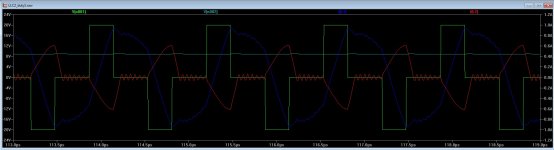
Yuks that's revolting, harmonic distortion terrible and they got CE for that ? well I guess it's self certified, perhaps you should report them!The following waveforms were obtained measuring voltage drop across a 0.1ohm shunt in series with mains supply. A 5KVA variac was used to get desired line voltage, and 3KVA isolation transformers were used to make it safe.
Low quality 120V mains was simulated by stepping 230V to 120V with variac before feeding 1:1 isolation transformers. Mid quality 120V mains was obtained with a setting close to 1:1 in variac and doing the 2:1 step-down with isolation transformers. Mid quality 230V mains was obtained with close to 1:1 setting in variac and 1:1 in isolation transformers.
This is what other brand calls "a PFC power supply". It's just a single stage rectifier with isolated output and wide input voltage range, implemented with a UCC2891/2/3/4 control IC not intended for PFC (fixed freq peak current control), waveform distortion is high as hell, harmonics are strong, worse than old diode bridge and caps, and instability arises at low quality mains. Steps in current waveform are observed at high-line high-load, maybe from a control loop with maybe only 16 discrete power levels possible. This is *cheap* design/copy (as Behringer) but a bit more rugged.
Pictures in order:
- line current @ 200W @ 120V low quality mains, onset of PFC regulations
- line current @ 350W @ 120V low quality mains falling to 115V
- line current @ 740W @ 120V low quality mains falling to 110V
- line current @ 860W @ 120V mid quality mains falling to 114V, stable overload
- line current @ 200W @ 230V mid quality mains, onset of PFC regulations
- line current @ 400W @ 230V mid quality mains falling to 226V
- line current @ 800W @ 230V mid quality mains falling to 221V
- line current @ 1100W @ 230V mid quality mains falling to 219V, hiccup in response to overload
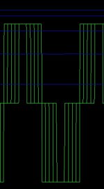
Thats very niceThese images were obtained from a prototype of the circuit and control approach explained at the beginning of the thread. The result is very low harmonics and phase shift, nearly sine current waveform at all conditions, also on low quality line. Incidentally my implementation uses same size power stage as "other brand", but optimized with the help of hundreds of hours of engineering and a custom control technique I developed. This results in 2x the part count, being the difference mostly in the amount of small parts.
Pictures in order:
- line current @ 200W @ 120V low quality mains, onset of PFC regulations
- line current @ 350W @ 120V low quality mains falling to 115V
- line current @ 700W @ 120V low quality mains falling to 110V
- line current @ 1400W @ 120V low quality mains falling to 100V, stable overload (PSU)
- line current @ 200W @ 230V mid quality mains, onset of PFC regulations
- line current @ 400W @ 230V mid quality mains falling to 226V
- line current @ 800W @ 230V mid quality mains falling to 221V
- line current @ 1600W @ 230V mid quality mains falling to 213V, stable overload (amplifier)
- line current @ 2KW @ 235V mid quality mains falling to 215V, had to reduce amplifier dummy load impedance to overload power supply at 230V
") clean, low harmonics and nice overload behavior Shame not all PFC's are this good
clean, low harmonics and nice overload behavior Shame not all PFC's are this good Oh, C for programming switchmode power electronics, so tell me, how much are taking to execute the instructions in C?.
The last time I checked its pretty fast, a few cycles delayed from assembly, with -O3 switch optimizations switch, the compiler does a fantastic job.I dont have my test jig but I measured a IIR filter (assembly VS C) using a standard STM32103 @ 3$ a piece and they perform very well (and that is a baseline model). I cannot comment to much about PIC, but the last time I opened up a garage door opener it used a PIC MCU.
I do think the PIC instruction set is easy and if you know it by heart then its better to stick with what you know as performance figures are deterministic.
Thank you for sharing your technique, I like the idea of tables prepared ofline fast to execute and fairly simple to generate with high level tools, excel would work for that too OMG even Fortran hahahaI'm programming it in pseudo code similar to C but more relaxed, then manually compiling it to assembler, this allows to choose optimization strategy for each code section. For support tasks such as generating precalculated tables based on parameters I use the good old BASIC. For example, for changing current limit I have to edit and run a BAS file (with external editor), then re-compile and program the MCU, as a pre-calculated table is used.
The last time I checked its pretty fast, a few cycles delayed from assembly, with -O3 switch optimizations switch, the compiler does a fantastic job.I dont have my test jig but I measured a IIR filter (assembly VS C) using a standard STM32103 @ 3$ a piece and they perform very well (and that is a baseline model). I cannot comment to much about PIC, but the last time I opened up a garage door opener it used a PIC MCU.
I do think the PIC instruction set is easy and if you know it by heart then its better to stick with what you know as performance figures are deterministic.
All CPU instruction sets are equivalent, no matter manufacturer or model, it's only that some instruction sets have big macros that others don't have or have an "isomeric" implementation (there are only a few ways in universe to do any calculation optimally, like mirror images of algorithms), and state-of-the-art converges. The challenge here is learning the fundamentals of low level computing, not learning the assembler and architecture of a particular MCU family. This is never understood with C, as C does not only come from this convergence between families of CPUs and problem computation routes, but from adaptation from human language.
Concerning periperals, all MCU families converge to the need of a finite set of built-in peripherals, with generalized features and connectivity functions, again there are no infinite options. One example is the 4x PSMC modules in PIC16F177x/PIC16F178x, that are originally intended for driving up to 4 half bridges, or 3 phases, but can also drive complex converters with more than 2 switches and 2 sequential states, because they included a synchronization function, that is enough together with some tweaks. Just in the limits of what the IC can do (I mean without having to resort to doing most of the work with external parts).
I think high-performance function-specific SMPS in the future is going to be like that, general purpose MCUs with SMPS periperals that can be adapted to many types of converter, and engineer's cross-skilled creativity (from sizing a LC network to deducting code to drive it).
Last edited:
Yuks that's revolting, harmonic distortion terrible and they got CE for that ? well I guess it's self certified, perhaps you should report them!
The module has a "200W" comment in PCB near power connector, close to its long term power handling without fan, and also the usual threshold for PFC requirement. If the module passed that regulation it was probably due to complying as a <200W device, 1KW max. power, as audio equipment can be tested at 1/8 power. A module capable of 2KW no longer matches that criteria, 2KW/8=250W. So what the hell, lets do a reference design of audio PFC, that others would find difficult to improve, I thought.
Ahh thank you for explaining the audio wayleave, I knew it had one from years ago but could not remember the details, I have just been amazed that so much band gear I repair for friends doesn't have PFC. I was a little confused by your two modules side by side photo, is that altogether one power supply or does it include a classD amp ? Apart from the PSMC modules in the 16F178x I managed to use all the op-amps and comparators, good way to mop up some more chips but makes juggling the pins fun. I write all my code in assembler for these chips, like you say when you are doing lots of calculations/second you need speed and also very well defined short and consistent interrupt latency. I have considered doing these things in an FPGA in VHDL/Verilog however then it becomes harder to do the system level stuff but I think if I got into Mhz switchers with fast transient response requirements that's the route I would use. I hope you have put your innovative psu to good useThe module has a "200W" comment in PCB near power connector, close to its long term power handling without fan, and also the usual threshold for PFC requirement. If the module passed that regulation it was probably due to complying as a <200W device, 1KW max. power, as audio equipment can be tested at 1/8 power. A module capable of 2KW no longer matches that criteria, 2KW/8=250W. So what the hell, lets do a reference design of audio PFC, that others would find difficult to improve, I thought.
All CPU instruction sets are equivalent, no matter manufacturer or model, it's only that some instruction sets have big macros that others don't have or have an "isomeric" implementation (there are only a few ways in universe to do any calculation optimally, like mirror images of algorithms), and state-of-the-art converges. The challenge here is learning the fundamentals of low level computing, not learning the assembler and architecture of a particular MCU family. This is never understood with C, as C does not only come from this convergence between families of CPUs and problem computation routes, but from adaptation from human language.
Concerning periperals, all MCU families converge to the need of a finite set of built-in peripherals, with generalized features and connectivity functions, again there are no infinite options. One example is the 4x PSMC modules in PIC16F177x/PIC16F178x, that are originally intended for driving up to 4 half bridges, or 3 phases, but can also drive complex converters with more than 2 switches and 2 sequential states, because they included a synchronization function, that is enough together with some tweaks. Just in the limits of what the IC can do (I mean without having to resort to doing most of the work with external parts).
I think high-performance function-specific SMPS in the future is going to be like that, general purpose MCUs with SMPS periperals that can be adapted to many types of converter, and engineer's cross-skilled creativity (from sizing a LC network to deducting code to drive it).
I'm interested in the basics. Where should I start first? Have you got suggestions for books, reports or app notes?
All CPU instruction sets are equivalent, no matter manufacturer or model, it's only that some instruction sets have big macros that others don't have or have an "isomeric" implementation (there are only a few ways in universe to do any calculation optimally, like mirror images of algorithms), and state-of-the-art converges. The challenge here is learning the fundamentals of low level computing, not learning the assembler and architecture of a particular MCU family. This is never understood with C, as C does not only come from this convergence between families of CPUs and problem computation routes, but from adaptation from human language.
Concerning periperals, all MCU families converge to the need of a finite set of built-in peripherals, with generalized features and connectivity functions, again there are no infinite options. One example is the 4x PSMC modules in PIC16F177x/PIC16F178x, that are originally intended for driving up to 4 half bridges, or 3 phases, but can also drive complex converters with more than 2 switches and 2 sequential states, because they included a synchronization function, that is enough together with some tweaks. Just in the limits of what the IC can do (I mean without having to resort to doing most of the work with external parts).
I think high-performance function-specific SMPS in the future is going to be like that, general purpose MCUs with SMPS periperals that can be adapted to many types of converter, and engineer's cross-skilled creativity (from sizing a LC network to deducting code to drive it).
Eva, many times you have told others, more money than brains, however I think you have "more time than money", which in adult hood translates to money.
The region you involved in is very deep and uncharted (for most), requires many hours of devotion, most people from hobbyist to commercial today use C today, as majority chips (like the PIC's and notably ARM) has a instruction FIFO stack deep enough to work with C, hell people even write mini RTOS, purely around interrupts. It seem your workflow model, takes all your code from a pseudo state machine, then performs translation into assembly.
I was looking at implementing AN1521,(MPPT charge controller). More interesting, look at the code, its all in C, all structured around the ISR's and its priority vector, using "C code" with this style of programming timing slices are robust and VERY predictable. I do prefer ARM stuff and learning alot about it, there NVIC and very very powerful, however the PIC's win in the peripheral department.
http://ww1.microchip.com/downloads/en/AppNotes/00001521A.pdf
Last edited:
Eva, many times you have told others, more money than brains, however I think you have "more time than money", which in adult hood translates to money.
The region you involved in is very deep and uncharted (for most), requires many hours of devotion, most people from hobbyist to commercial today use C today, as majority chips (like the PIC's and notably ARM) has a instruction FIFO stack deep enough to work with C, hell people even write mini RTOS, purely around interrupts. It seem your workflow model, takes all your code from a pseudo state machine, then performs translation into assembly.
I was looking at implementing AN1521,(MPPT charge controller). More interesting, look at the code, its all in C, all structured around the ISR's and its priority vector, using "C code" with this style of programming timing slices are robust and VERY predictable. I do prefer ARM stuff and learning alot about it, there NVIC and very very powerful, however the PIC's win in the peripheral department.
http://ww1.microchip.com/downloads/en/AppNotes/00001521A.pdf
Frankly AN1521 has the complexity of connecting a battery to a bulb, it is in no way comparably with the complexity of the resonant pfc converter explained here nor a gti that I have implemented in machine code. Not just complexity but requirement for a high rate of processing and reactivity to changing conditions.
It so happens I am a retired engineer and spend months and even years perfecting designs, that is my prerogative and not for the likes of you to cast aspersions on how others spend there time. Perhaps your should try and make a positive contribution to the discussion instead of wasting peoples time bleating on about your favorite programming language.
Frankly AN1521 has the complexity of connecting a battery to a bulb? Oh really? retired engineer Oh really? with that attitude its a good thing.
Please show us some equivalent work with your bombastic show off attitude.
engineer? and you assumed this? please behave and stop showing off.Great chips but the IO is a bit hair raising at times, I recently got caught with mysterious offsets on some analogue pins that turned out to be the internal pullups! I had stupidly assumed these would be disabled on an analogue pin
Last edited:
These modules are multi-channel class D amplifiers with power supply, another set of nice quizzes to solve in secondary side. So you say you have already used Microchip MCUs with PSMC? There is a new PIC16 flavor which includes remappable pins as in PIC32. Not much problem with the pins in the other parts as 4~6 layer PCB is used, and there were combinations possible to get optimum pinout (like current comparator IN+ and IN-, or GND, not very far one from another). Some inputs required external circuits for blanking, as the PSMC do not include enough options in this field.Ahh thank you for explaining the audio wayleave, I knew it had one from years ago but could not remember the details, I have just been amazed that so much band gear I repair for friends doesn't have PFC. I was a little confused by your two modules side by side photo, is that altogether one power supply or does it include a classD amp ? Apart from the PSMC modules in the 16F178x I managed to use all the op-amps and comparators, good way to mop up some more chips but makes juggling the pins fun. I write all my code in assembler for these chips, like you say when you are doing lots of calculations/second you need speed and also very well defined short and consistent interrupt latency. I have considered doing these things in an FPGA in VHDL/Verilog however then it becomes harder to do the system level stuff but I think if I got into Mhz switchers with fast transient response requirements that's the route I would use. I hope you have put your innovative psu to good use
I'm interested in the basics. Where should I start first? Have you got suggestions for books, reports or app notes?
No, you have to study different families of MCUs and do some implementations of real-world functions and converters. Only this creates the brain structures for abstraction/generalization.
The last time I checked its pretty fast, a few cycles delayed from assembly, with -O3 switch optimizations switch, the compiler does a fantastic job.I dont have my test jig but I measured a IIR filter (assembly VS C) using a standard STM32103 @ 3$ a piece and they perform very well (and that is a baseline model). I cannot comment to much about PIC, but the last time I opened up a garage door opener it used a PIC MCU.
I do think the PIC instruction set is easy and if you know it by heart then its better to stick with what you know as performance figures are deterministic.
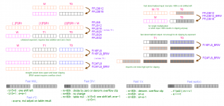
I wrote a custom SMPS floating point library for 8 bit PIC, 8 bit for exponent and 8 bit for mantissa, with an optimized call/parameter interface, that allows multiplications, divisions squaring and square root of voltages and currents in record times, also chained calculations with minimum overhead. You won't be able to do this in C, since first imposition is a fixed call/parameter interface.
In practice it means you will have to use a 16 or 32 bit MCU to get comparable processing power, but those don't have comparators, op-amps or PSMC, and the reason is chip construction and expected target applications. More complex MCUs use different fabrication process which is not so suitable for implementing CMOS op-amps and comparators in the same die. Company development teams are also lacking good analog brains in the more complex MCU families, for example in PIC32MX some of the analog functions (variable voltage references with DAC) were faulty by design, and not fixed until next family.
I know more than an instruction set, about 4. This is the point where the need for generalization/abstraction arises. I know digital computing by heart instead. First decision is choosing a suitable instruction set to minimize penalties for a certain application. For secondary side MCU I choose 32 bit because I knew there was going to be a lot of precision multiplications action, not due to the PSU which is a minimal task, but due to the other tasks involved, and MIPS is a highly rationalized standard.
btw: If you want to implement that AN1521 create a thread and start by studying the converter topology used and how to optimize it for min. losses and min. natural resource usage, and how to drive it (simulation model).
Attached picture shows call interface of mini-floating point conversions in the library I developed.
Attachments
Last edited:
Also, I said the converter proposed comes after LLC for a reason. LLC is the introduction into resonant principles, but works fine with linear control. Other converters using some form of resonant loss reduction but working OK with linear control are useful for the same learning. Please do not ask for "high grade" in SMPS when "low grade" is not completed. This is "high grade" in SMPS.
I wrote a custom SMPS floating point library for 8 bit PIC, 8 bit for exponent and 8 bit for mantissa, with an optimized call/parameter interface, that allows multiplications, divisions squaring and square root of voltages and currents in record times, also chained calculations with minimum overhead. You won't be able to do this in C, since first imposition is a fixed call/parameter interface.
In practice it means you will have to use a 16 or 32 bit MCU to get comparable processing power, but those don't have comparators, op-amps or PSMC, and the reason is chip construction and expected target applications. More complex MCUs use different fabrication process which is not so suitable for implementing CMOS op-amps and comparators in the same die. Company development teams are also lacking good analog brains in the more complex MCU families, for example in PIC32MX some of the analog functions (variable voltage references with DAC) were faulty by design, and not fixed until next family.
I know more than an instruction set, about 4. This is the point where the need for generalization/abstraction arises. I know digital computing by heart instead. First decision is choosing a suitable instruction set to minimize penalties for a certain application. For secondary side MCU I choose 32 bit because I knew there was going to be a lot of precision multiplications action, not due to the PSU which is a minimal task, but due to the other tasks involved, and MIPS is a highly rationalized standard.
btw: If you want to implement that AN1521 create a thread and start by studying the converter topology used and how to optimize it for min. losses and min. natural resource usage, and how to drive it (simulation model).
Attached picture shows call interface of mini-floating point conversions in the library I developed.
Hey thanks for this!, now I know what was keeping busy in 2016
Your library structure looks similar to a q15 format, if I'm correct? this how we do brute force signal processing on a resource limited MCU.
Thanks for the tips for AN1521.
hola Eva,
I have been playing with a mix of PWM and LLC as I like the low coupling of the LLC for noise reasons, but don't like the LLC for it's limited input voltage range. So I came up (and found later in litterature) with a 3 level drive. the idea was to sync it with a digital word clock to minimize interference, that's why i had only discrete pwm duties.( and do some post regulation later, for low power appplication. this could do pfc as well I guess.
below a sim showing the drive voltage. at duty=0.5 it is a standard LLC drive. you need a 3rd switch that can handle bidirectional voltages.
Attachments
3 level is (at least) a 4 transistors and 2 diodes power stage, 2 transistors grounded to different fixed potentials, 2 transistors grounded to floating potentials. I already tried this for 230V to 120V quasi-sine inverter, being this mostly the field of application.
In SMPS there are undesirable losses during middle stage, transistor+diode are conducting close to peak current.
The single stage isolated PFC problem can only be solved by flyback, or a more complex mix of boost inductor and transformer-capacitor coupling for higher powers, in other words, non-linear converters and non-linear control.
The LLC was introduced due to lower EMI and the need to market new control ICs and power supply designs, not because it shines in any other field.
In Spain in general functional creativity is blocked by social relationships and the influence of primitive matriarchy epigenetics (brain microcode). Most people use half brain for relationships and half brain for technology, this is imposed by women directly, and indirectly by women through other men. This only allows creative copying. I had to overcome this problem to be able to design something new and functionally superior. You would not like the things you would have to do to follow this path.
btw: You cannot close mentally the finite set of few possible converters for an application, because this form of closing sets of finite probabilities is being hacked by your relatives to inject other phantom probabilities, in order to exploit you, and you do that too, as a way to stay together losing half creativity. Half brain human, half brain reptile.
Last edited:
- Status
- This old topic is closed. If you want to reopen this topic, contact a moderator using the "Report Post" button.
- Home
- Amplifiers
- Power Supplies
- The ultimate amplifier SMPS. What comes after LLC? Single stage PFC.