Member
Joined 2009
So if I understand correctly you process your entire music library to contain an allphase shift that is inverse to your speakers'. When the file is played through your system it will be in the correct phase.
When you stream new music like let's say Internet Radio, it will be played with the system's inherent phase shift.
I've read about this approach but I wasn't aware of anybody using it. How did you verify that it's working correctly? There's a theory that a buffer can be used to to do the reverse processing in 'real time' with a reasonable delay. If it's indeed possible a DSP implementation will not be hard. What are your thoughts on that?
Correct. Latency aside, the difficulty with getting good quality out of time reversed IIR in real time is the memory and processing power requirements. It's a PC or audio SHARC kind of thing, though it's possible to cram it into Cortex M4s if you really want. So there's a certain convenience to setting block size = file size and doing the processing at rip and burn time. Also, if I recall correctly, Refined Audiometrics has a patent on windowing the blocks together to avoid discontinuities.
Posts 1 and 3 in this thread have the measurements validating the phase corrections. All I did was transfer the settings over to Cross Time DSP.
Posts 1 and 3 in this thread have the measurements validating the phase corrections. All I did was transfer the settings over to Cross Time DSP.
Go for it. I've already done the analysis for my personal build but I'm sure others will find it handy to have a one stop tool.I can post up my dipole speaker configurator...
Hi twest,
It seems you've taken good care of the gain structure including the bit depth in digital domain. As I've seen very few people pay enough attention on that. Great job!
With only 2 posts, under load, there'll be a lateral force pulling the posts inward, thus a stress at the base of post. Or that point will become a pivot. So additional care should be taken to hold the posts in position.
To avoid additional complexity, a simple lintel is still preferable. It releases side loads on the posts. This is the simplest construction I can think of:
http://www.diyaudio.com/forums/multi-way/159731-beautiful-swingin-speaker-12.html#post2672403
Such support works almost perfectly. Stone dead on the frame while the cone is moving hard.
OTOH, however, I was not satisfied with other aspects of that setup, so I moved to other solution.
The 2 rigid small feet as pivot with soft ones for holding it straight up is a little transformation from the previous all-soft-feet trials. Both StigErik and I encountered the problem of compressed pads that no longer providing proper softness. So this time I give it a rigid support against gravity, keep it swing-able, and use other soft feet for compliance.
It seems you've taken good care of the gain structure including the bit depth in digital domain. As I've seen very few people pay enough attention on that. Great job!
In particular, the idea of two posts with a sling between them to hold the driver magnet seems worth trying. That's about halfway between regular post and lintel construction and some of the suspensions Stig Erik used for his subs before he switched over to bicycle tubes. It's possible a rope or webbing sling might provide all the flex needed just by itself.
With only 2 posts, under load, there'll be a lateral force pulling the posts inward, thus a stress at the base of post. Or that point will become a pivot. So additional care should be taken to hold the posts in position.
To avoid additional complexity, a simple lintel is still preferable. It releases side loads on the posts. This is the simplest construction I can think of:
http://www.diyaudio.com/forums/multi-way/159731-beautiful-swingin-speaker-12.html#post2672403
Such support works almost perfectly. Stone dead on the frame while the cone is moving hard.
OTOH, however, I was not satisfied with other aspects of that setup, so I moved to other solution.
The 2 rigid small feet as pivot with soft ones for holding it straight up is a little transformation from the previous all-soft-feet trials. Both StigErik and I encountered the problem of compressed pads that no longer providing proper softness. So this time I give it a rigid support against gravity, keep it swing-able, and use other soft feet for compliance.
Attached. Fairly intuitive, I should think.Correct. Latency aside, the difficulty with getting good quality out of time reversed IIR in real time is the memory and processing power requirements. It's a PC or audio SHARC kind of thing, though it's possible to cram it into Cortex M4s if you really want. So there's a certain convenience to setting block size = file size and doing the processing at rip and burn time. Also, if I recall correctly, Refined Audiometrics has a patent on windowing the blocks together to avoid discontinuities.
Posts 1 and 3 in this thread have the measurements validating the phase corrections. All I did was transfer the settings over to Cross Time DSP.
Go for it. I've already done the analysis for my personal build but I'm sure others will find it handy to have a one stop tool.
Attachments
Last edited:
Thank you. I've found DAC direct to the average 25-30dB gain power amp hits quantization problems pretty quick in 16 bit. Kind of surprising that people put up with this. I'd think amps with variable gain would be more common; turn the gain down to the 0dB to 6dB range for typical listening and crank it when you want loud. Though horns start to call for attenuation rather than gain---I'd love it if this system had even mediocre horn efficiency as then I could just run it off high current op amps directly. Would be simpler to design and easier to layout nicely in two layers than the composite amps I've been building.Great job!
Specifically, the torque at the base is the dot product of the sling/rope/cord/cable/wire/whatever tension and the vector from the base to the attachment point on the post. If you use a curved post you can take the dot product to zero, though the member of course has to handle the internal torque on the curve. Agree lintels are great for building something quick but, well, I already have a pair. So I'm thinking more in terms of a furniture grade redo with materials like hardwoods, anodized aluminum, and granite. The smallest architectural channel I can easily get is 0.125" wall 0.75 x 0.75" 6061. The 18SWS1100s only weigh 15.4kg each, so the issue with structural strength is more likely to be machining things down enough I can actually bend them into arcs. Wouldn't surprise me if it turned out to be easier to do a composite layup.With only 2 posts, under load, there'll be a lateral force pulling the posts inward, thus a stress at the base of post.
A simpler to build option which offers a less bulky appearance than a lintel is to cross brace the posts below the driver. Bar stock, drill and tap, bolts, problem solved. Done right, the braces would be mostly hidden from view. And I have some itty bitty turning blocks intended for sailboats which would do nicely for allowing a line to run over the top of the posts so the bolins it's made off with could be hidden in the plinth.
Seems like everybody who tries that hits that problem. Machine isolation feet should hold up fairly well, but they're not cheap. And little ones for light weight loads are hard to find.Both StigErik and I encountered the problem of compressed pads that no longer providing proper softness.
Last edited:
I'd need to see measurements and a system description comparable to posts 1 and 3 in this thread to provide an informed response. A/Bing speakers has its uses but if one's striving for fidelity it makes the most sense to design at the system level and repartition the solution as needed. My anecdotal experience is studio monitors tend to be above average among box speakers---pro audio has a way of offering noticeably better price/performance than hi-fi---but I'm kind of fussy about consistent directivity and flat SPL so I prefer dipoles. You can't see it in the photos but my current listening room is asymmetric with an open doorway to the kitchen opposite the window at the side of the speakers. Conveniently, the doorway lines up with the dipole null; masking it out that way helps quite a bit compared to omni bass. Doesn't make the fridge any quieter, however.
Last edited:
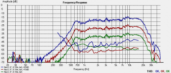
Something I've been interested in lately is DAC antialiasing filters. Per Fourier, the steeper the frequency domain rolloff and the narrower the bandwidth the longer the impulse response. So it's interesting to use slower rolloff filters---Wolfson's time domain paper is one of the better introductions to the topic---which in turn means some amount of ultrasonic content reaches the amplifiers and tweeters. How much depends on the choice of DAC and filter, but one's likely interested in the 50 to 100kHz range. As I'm not aware of tweeter distortion data in the ultrasonic range (Zaph's graphs, for example, all stop at 10kHz) I thought it'd be worthwhiel to update the Neo3 data in post 1 of this thread with a higher sampling rate.
Take the attachment with some salt. The mic cal used stops at 25kHz, the mic has begun to roll off at that point, and it's likely the breakup at 35kHz is the mic and not the Neo3--it doesn't appear in BG's published data. If I've got my calibration right the peaks of the curves at 9.1kHz should be 90, 80, and 70dB SPL. Those issues aside, the implication's there's not enough going on in the ultrasonic range for IMD downmod to cause audible problems when the driver sees a flat PSD. Since music PSDs are typically 1/f and single speed (44.1 or 48) slow rolloff stopbands start around 35kHz with 100dB or more of attenuation any problems lurking under the measurement limit here are likely to see 50dB or more of attenuation. So, unlike some tweeters which have high Q breakups just outside the audio band, ultrasonic handling on the Neo3 looks fine.
Should anyone be inclined to loan me an Earthworks QTC50 I'll be happy to remeasure.")
Take the attachment with some salt. The mic cal used stops at 25kHz, the mic has begun to roll off at that point, and it's likely the breakup at 35kHz is the mic and not the Neo3--it doesn't appear in BG's published data. If I've got my calibration right the peaks of the curves at 9.1kHz should be 90, 80, and 70dB SPL. Those issues aside, the implication's there's not enough going on in the ultrasonic range for IMD downmod to cause audible problems when the driver sees a flat PSD. Since music PSDs are typically 1/f and single speed (44.1 or 48) slow rolloff stopbands start around 35kHz with 100dB or more of attenuation any problems lurking under the measurement limit here are likely to see 50dB or more of attenuation. So, unlike some tweeters which have high Q breakups just outside the audio band, ultrasonic handling on the Neo3 looks fine.
Should anyone be inclined to loan me an Earthworks QTC50 I'll be happy to remeasure.
Attachments
Something I've been interested in lately is DAC antialiasing filters. Per Fourier, the steeper the frequency domain rolloff and the narrower the bandwidth the longer the impulse response. So it's interesting to use slower rolloff filters
I have always found many of the modern V out dac chips to sound best with no analog ultrasonic filter following them. I also run them direct out through a high quality blocking cap with no buffer. And, have also reduced the value of the output coils in my Tripath amps to a minimum. Ultrasonic noise above 200kHz is apparently no problem and the gains in reduced parts count in the signal path far outweigh any losses.
It's been a while since I looked at the Tripath parts but, from what I recall, their loop gain probably drops below unity before 100kHz. So I would not expect the low order, out of audio band lowpasses typically used with DACs to be audible---commonly used cutoffs in the 50 to 200kHz range likely have more bandwidth than the amplifier and hence do little or no signal shaping compared to the amp. A corollary is the power amplifier likely lacks the loop bandwidth to respond to images. Is this an ABX or blind A/B result? Do you have a system schematic, layout, or measurements you can link?
Last edited:
All of my comments are based on sighted AB listening. The coils were discussed at length in many different threads. These among them.
.
http://www.diyaudio.com/forums/class-d/143669-sure-electronics-new-tripath-board-tc2000-tp2050.html
.
http://www.diyaudio.com/forums/class-d/162765-coil-pile.html
.
My preference for running my dac chips direct out with no analog filter or buffer has been discussed here.
.
http://www.diyaudio.com/forums/digi...5-4396-ultrasonic-noise-spectrum-graphic.html
.
http://www.diyaudio.com/forums/digital-line-level/137231-ak4395-vs-ak4396-listening-comparisons.html
.
http://www.diyaudio.com/forums/digital-line-level/144166-ak4396-best-solution-output-stage.html
.
http://www.diyaudio.com/forums/digital-line-level/137976-experience-diy-dac.html
.
http://www.diyaudio.com/forums/class-d/143669-sure-electronics-new-tripath-board-tc2000-tp2050.html
.
http://www.diyaudio.com/forums/class-d/162765-coil-pile.html
.
My preference for running my dac chips direct out with no analog filter or buffer has been discussed here.
.
http://www.diyaudio.com/forums/digi...5-4396-ultrasonic-noise-spectrum-graphic.html
.
http://www.diyaudio.com/forums/digital-line-level/137231-ak4395-vs-ak4396-listening-comparisons.html
.
http://www.diyaudio.com/forums/digital-line-level/144166-ak4396-best-solution-output-stage.html
.
http://www.diyaudio.com/forums/digital-line-level/137976-experience-diy-dac.html
Some of those threads are over 100 pages long, but I looked through the first few pages of each and didn't see schematics or measurements (other than the repost of AKM's out of band noise figure) or discussion of lowpass filtering in DAC output buffers. So I figure it's sighted AB of an AKM4396 + SP2050 versus [something] + SP2050 with a population size of one. That's, umm, let us say, not a statistically significant result. Makes it kinda hard to base design reasoning on.
My swinging mids
The swinging dipole/max cancellation thing had me thinking, what can I do with mids?
4th at 250, 2nd LP at 1k
The swinging dipole/max cancellation thing had me thinking, what can I do with mids?
An externally hosted image should be here but it was not working when we last tested it.
4th at 250, 2nd LP at 1k
An externally hosted image should be here but it was not working when we last tested it.
Cleaned up the felt layout- there's now a semicircular cutout relieved from the felt, which has been trimmed and layed-out to avoid restricting forward radiation from either driver. The felt is necessary to damp any scattering from the horn body and to absorb any misbehaving highs from the heil.
Hmm, actually, HOLMImpulse uses an exponential swept sine with something like the usual 3dB/octave falloff. Presumably its pause after taking measurements is when the correction filter for this is applied and some portion of the measured pre-ringing the result of the linear phase combination of the measurement and its correction---more on that in this paper.It's interesting to note most of the preringing is slower than the rest of the impulse and is roughly a 1.7kHz wave shape. There's a 30 degree phase movement around the Neo3 to Neo10 crossover; that could be the cause of incomplete cancellation.
- Status
- This old topic is closed. If you want to reopen this topic, contact a moderator using the "Report Post" button.
- Home
- Loudspeakers
- Multi-Way
- the three way nude swinging dipole thread