This amp started out in the SS forum as part of another thread, but now that I have actual measurements, and they agree remarkably well with prediction, I thought I would share it here in this forum as we love simple circuits here. Mr Pass has asked the question "What is the sound of one transistor clapping?" in his description of the Zen amp, well this sort of tries to answer that with two transistors. I think what we will see is that simplicity in the circuit really can translate to great sound quality. This is a headamp, so requirements are not so tough from power standpoint, but what you do have should be very clean and nice sounding and hence pure Class A is the way to go. Aksa (Hugh) helped me with the inspiration for this design, and some credit has to also go to Juma who gave the impetus to make a preamp with the BF862 JFET, and Easphyx who proposed a small tin of mints amp using a ZVN4306 as the output device. Here is a design that uses a single BF862 JFET on the input and single N channel MOSFET for the output. With only one device on input and output stages, we keep things simple and eliminate the need to match devices.
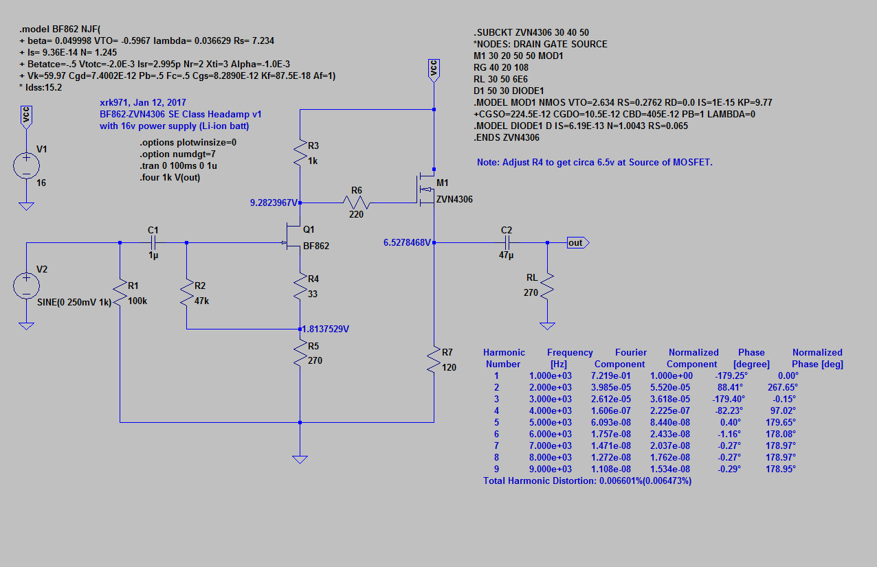
Here is the schematic and I am using the Diodes Inc (Zetex) .subckt model for the MOSFET, and the BF862 model is from ElFishi's thread. The single ended design is nice because an output cap eliminates the danger of DC rail blowing out expensive headphones. Voltage is set nominally at 16v to 18v depending on the batteries you use. A pair of "9v" Li-ion rechargeable batteries is 16.8v fully charged but quickly drops to about 16v. I am using a Panasonic OSCON solid polymer 47uF 25v ouput cap (SMT) bypassed with a 0.47uF 100v MKP film from Vishay. The input cap is a 1uF 230v MKT from CBB. MOSFET is part ZVN4306GTA from Digikey, and BF862 is marked 2AW with small 63 sideways. Left and right channels matched for same (5%) Idss on BF862. No matching done on VZN4306's.
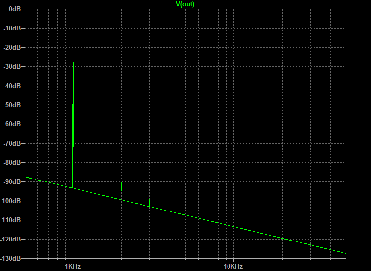
Here is predicted FFT with about 1.4v p-p output:
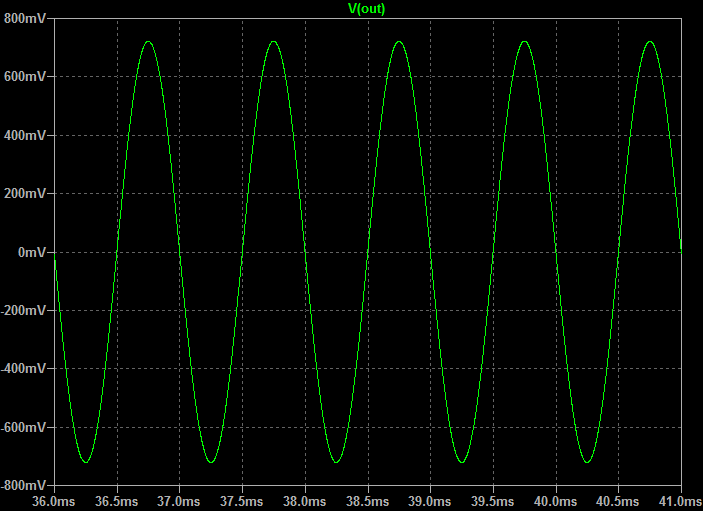
Here is predicted 1kHz sine wave at 1.4v p-p:
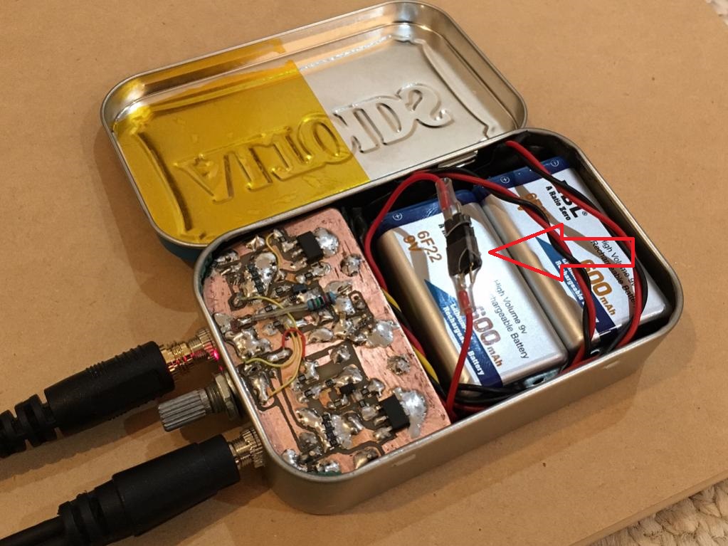
Here is the SMT implementation with a hand etched PCB using a Sharpie marker for the resist mask:
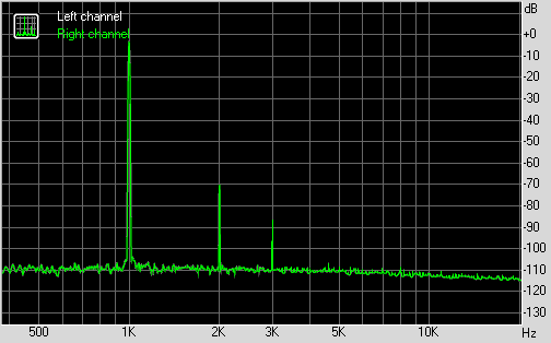
And here is the FFT measurement (using UCA202 interface and RightMark software) on a 270ohm resistive load (SMT 5% metal thin film):
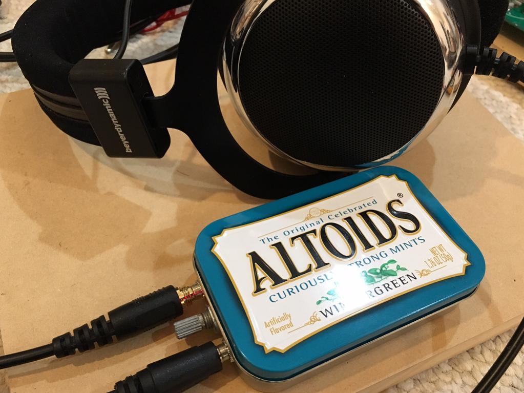
The sound of the amp through my Beyerdynamic DT880 (250ohm) headphones is wonderful. Very clear, bass is superb, it is very quiet when no signal present, no hiss, no noise - cannot tell it is on. As a practical class A portable headphone amp, it works there as well as I have demonstrated in a real world test which requires 4 hrs of playtime on a long bus commute. It gets warm - a good handwarmer for cold day, but not hot. The bias current is circa 50mA to 60mA depending on battery level.
I should record some sound clips by digitizing the resulting waveform on a 270R resistor and post it for folks to listen to the sound of two transistors clapping. I know that the sound is indeed special.
Here is the schematic and I am using the Diodes Inc (Zetex) .subckt model for the MOSFET, and the BF862 model is from ElFishi's thread. The single ended design is nice because an output cap eliminates the danger of DC rail blowing out expensive headphones. Voltage is set nominally at 16v to 18v depending on the batteries you use. A pair of "9v" Li-ion rechargeable batteries is 16.8v fully charged but quickly drops to about 16v. I am using a Panasonic OSCON solid polymer 47uF 25v ouput cap (SMT) bypassed with a 0.47uF 100v MKP film from Vishay. The input cap is a 1uF 230v MKT from CBB. MOSFET is part ZVN4306GTA from Digikey, and BF862 is marked 2AW with small 63 sideways. Left and right channels matched for same (5%) Idss on BF862. No matching done on VZN4306's.
Here is predicted FFT with about 1.4v p-p output:
Here is predicted 1kHz sine wave at 1.4v p-p:
Here is the SMT implementation with a hand etched PCB using a Sharpie marker for the resist mask:
And here is the FFT measurement (using UCA202 interface and RightMark software) on a 270ohm resistive load (SMT 5% metal thin film):
The sound of the amp through my Beyerdynamic DT880 (250ohm) headphones is wonderful. Very clear, bass is superb, it is very quiet when no signal present, no hiss, no noise - cannot tell it is on. As a practical class A portable headphone amp, it works there as well as I have demonstrated in a real world test which requires 4 hrs of playtime on a long bus commute. It gets warm - a good handwarmer for cold day, but not hot. The bias current is circa 50mA to 60mA depending on battery level.
I should record some sound clips by digitizing the resulting waveform on a 270R resistor and post it for folks to listen to the sound of two transistors clapping. I know that the sound is indeed special.
Last edited:
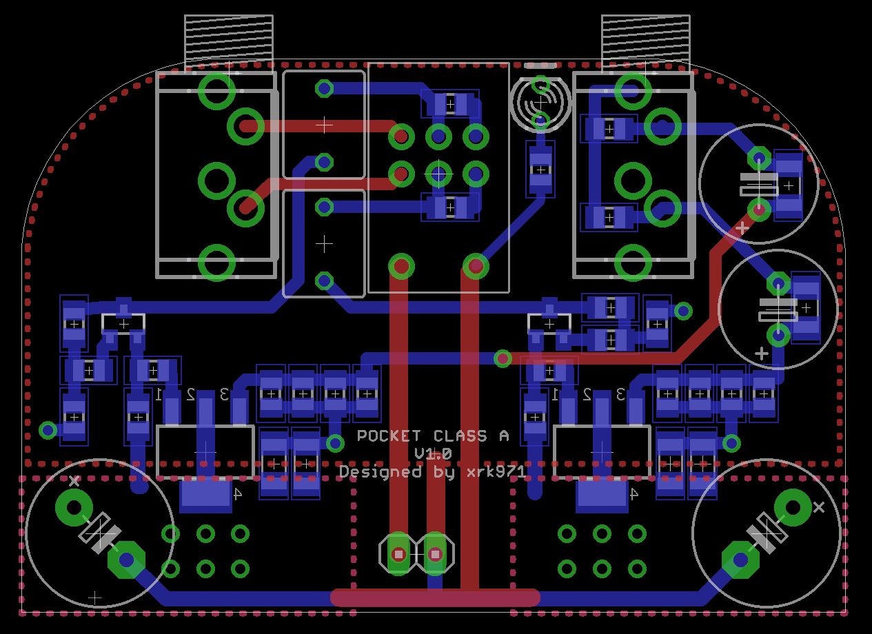
We are on our way to a real PCB. This one designed by BDHM with initial footprint provided by Agdr (pot and 3.5mm jacks, and outline):
http://www.diyaudio.com/forums/head...2-based-se-class-headamp-without-heat-17.html
http://www.diyaudio.com/forums/head...2-based-se-class-headamp-without-heat-17.html
Thank you, Mr. Pass. I think the simulation and reality are actually very close except for absolute magnitude of the distortion. I wonder what I can do to bring the distortion values closer to what simulation predicts? Or is this mostly result of models of the actives that are not accurate? The prediction and measurement of just H2 and a little H3 is very encouraging though.
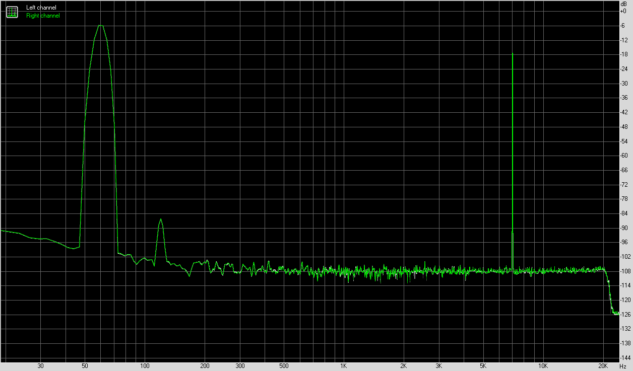
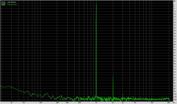
I retook the data with a fresh set of batteries and in a different room. For some reason, the results are now even better. Or is it "burn-in"?
FFT (it's very close to the prediction now):

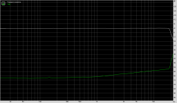
Freq Resp. and THD (0.012%) - the frequency response falloff at high frequency is actually due to sound card response:

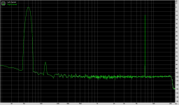
IMD+N (0.04%):
FFT (it's very close to the prediction now):
Freq Resp. and THD (0.012%) - the frequency response falloff at high frequency is actually due to sound card response:
IMD+N (0.04%):
Attachments
Last edited:
... some credit has to also go to Juma who gave the impetus to make a preamp with the BF862 JFET,
Actually you are using exact copy of my gain stage from post #346 of that thread.
I didn't give the impetus but the circuit itself.
Resistor loaded source follower is beyond trivial.
Last edited:
Thank you, Mr. Pass. I think the simulation and reality are actually very close except for absolute magnitude of the distortion. I wonder what I can do to bring the distortion values closer to what simulation predicts? Or is this mostly result of models of the actives that are not accurate? The prediction and measurement of just H2 and a little H3 is very encouraging though.
Simple, check/change the bloody models. They are almost always based on the 25C curve.
Do your own measurements under the conditions they will be used in and modify the models to match the real measurements.
Not hard at all, just a bit of extra time to do the measurements.
This is becoming my pet peeve. People are using models without even checking that they match reality.
Last edited:
Actually you are using exact copy of my gain stage from post #346 of that thread.
I didn't give the impetus but the circuit itself.
Resistor loaded source follower is beyond trivial.
Juma,
I wasn't trying to say the circuit wasn't yours - the preamp from that post is what I used for my DAO amp at your suggestion. Then Hugh suggested to use just the input stage BF862 and put a power mosfet at the output and no CCS. so you are right - topology is essentially the same with one less active and I reduced R4 from 1M to 47k - it sounded better and the predicted harmonic profile then became what it currently is with H2 dominant and little H3.
I don't disagree that it's a trivial circuit. But amazing what a trivial circuit can sound like. Certainly makes it a joy to build.
Last edited:
Simple, check/change the bloody models. They are almost always based on the 25C curve.
Do your own measurements under the conditions they will be used in and modify the models to match the real measurements.
Not hard at all, just a bit of extra time to do the measurements.
This is becoming my pet peeve. People are using models without even checking that they match reality.
Funny how the measurement matches prediction a lot more now after using fresh batteries and RCA outputs instead of headphone outputs.
No not really. I'm still annoyed. HahahahahaFunny how the measurement matches prediction a lot more now after using fresh batteries and RCA outputs instead of headphone outputs.
The improvement could be due to many reasons.
Anyway, nice headphone amp mate. I'd do it slightly differently, not necessarily better though.
You should hang out here, no need to collaborate with the infidels out there (Juma excluded of course (ie Juma is not an infidel)).
")
Last edited:
No not really. I'm still annoyed. Hahahahaha
The improvement could be due to many reasons.
Anyway, nice headphone amp mate. I'd do it slightly differently, not necessarily better though.
You should hang out here, no need to collaborate with the infidels out there (Juma excluded of course (ie Juma is not an infidel)).
Thanks man, but it would seem that hanging out around here may not be so welcome given that someone voted 1 star this early in the game.
Thanks man, but it would seem that hanging out around here may not be so welcome given that someone voted 1 star this early in the game.
1 Star is better than none.
I usually get no stars for my threads. Hahahaha
Edit: I just gave ya 4 stars to make ya feel better. Gee I am a nice guy.
Last edited:
Sound Clip of Two Transistors Clapping
I am playing a track through the outputs of my UCA202 DAC, which then feeds the Pocket Class A headamp input, the output of which drives a 270R resistor, and the DAC input records the voltage across this resistor as generated by the amp. So you are "hearing" what the amp sounds like to a purely resistive load. I then convert that digital recording of the resistor voltage to a 320kbit MP3 sound file. In order to break the file size limit, the MP3 file is renamed with an .asc extension. Just rename the extension back to .MP3 in order to listen. So here is a virtual audition of two transistors playing through a perfect headphone with flat response and flat impedance.
Let me know what you think.
This will be interesting to record several different amps using this method and you could then do a virtual audition of the amp, as if you had a perfect resistive load headphone. So the contributions to sound quality are purely the result of the amp as all things in in the signal chain stays the same.
Attachments
Last edited:
The clip sounds great X. Listened through DT770 Pro 250s. I may have to try this little amp on some vero board or similar. Quite a simple circuit.
You making PCBs to sell?
Glad you think it sounds good! I will probably have a GB of this amp soon. Having it to carry around in your pocket is really fun. I mean who would have thunk that one could take a SE class A amp on the road with a pair of 9v batteries?
Glad you think it sounds good! I will probably have a GB of this amp soon. Having it to carry around in your pocket is really fun. I mean who would have thunk that one could take a SE class A amp on the road with a pair of 9v batteries?
Count me in for a few boards for the gb. This is just what I need for nice weather hammock listening sessions
What 60Hz are you talking about? I posted an earlier graph of the FFT of my Salas DC3G which is powered by a mains trafo but removed it because I found a problem with oscillation. That FFT had a 60Hz bump. I fixed the oscillation issue - needed a volume pot to load the input gate sufficiently. Here is the Salas DC3G FFT without oscillation. It is predominantly H3, albeit low at about -90dB. And here is a soundclip of the DC3G as recorded from a 270R metal thin film resistor.
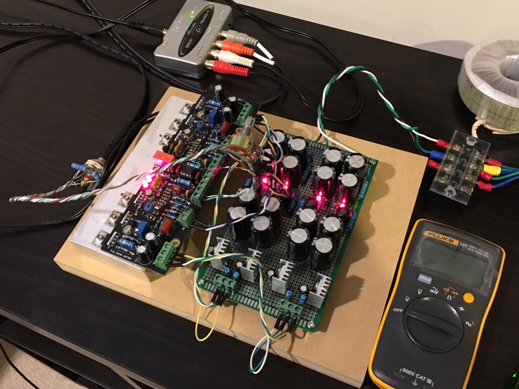
FFT:
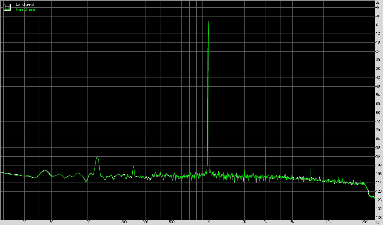
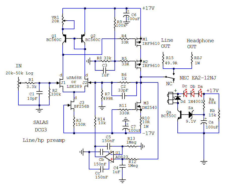
Change extension from .asc to .mp3 in order to listen. How does this amp sound in comparison? It is a much more complex amp, DC coupled with opamp servo and CCS's with dual LTP input:
FFT:
Change extension from .asc to .mp3 in order to listen. How does this amp sound in comparison? It is a much more complex amp, DC coupled with opamp servo and CCS's with dual LTP input:
Attachments
Last edited:
- Status
- This old topic is closed. If you want to reopen this topic, contact a moderator using the "Report Post" button.
- Home
- Amplifiers
- Pass Labs
- The Sound of Two Transistors Clapping