The 0.1uF decoupler is across the Zobel effectively shorting the 1 Ohm damping higher band. The small resistor you put there is a proper move that I recommend also in difficult interfacing cases. Scope it and if still not well damped a 100uF cap across the sense out wires can be of further aid.
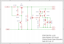
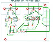
Reflecting back to the Reflektor when I chanced on this Kon San's account in his Japanese blog. Its about a +5V one for his DAC as attached. Google translation of the parts selection and his impressions is:
"I increased 0.47uF to 0.1uF were conventional ones Zobel circuit placed in the immediate vicinity of the IRF640 which circuit (2) shunt. I made this because there is no hand in the measures listed in Diyaudio, 1uF, but it seems really good too.
Was in 8200uF × 2 of (generally from Kemi Sun) 10000uF conventional electrolytic capacitor that is connected in parallel with the semi-fixed resistor and 1KΩ 1S1588 that make up the reference voltage (3). In the LE series of Nichicon, which is similar to what is referred to as Sanyo (Panasonic) and OS configuration.
The results.
I can hear without aging, the effect is enormous. Throb feeling overflows, and listen to the live recording version of "Tannhauser" Wagner, it sounds as if the singer is singing at the position of 3 meters in front of me. Sound is clear and vivid. Descriptive power is a masterpiece majestic panorama seen the stage to take in hand. It is the impression that "sang" all anyway.
The sound is so different from what the regulator, I was nothing but surprised. I came out a sound that was really worried about it until now and can not afford lightly. No one was feeling stiff and sound before. Without having to worry about anything, just be soaked to the hilt with music. This is not a happy thing. It's enough that I think it is not necessary to make an amp anymore, no reason to make is to have disappeared, and I wonder if anything was lost, it becomes a little anxious to reverse.
It has been decided that the bug is to turn out to mess with, I would like to thank and I was able to meet the regulator in any case also a really good anyway.
Due to the small number of parts, I will work with no trouble using the MOS-FET specified, if you take even a decent pair of tiger to use a current mirror circuit.
Noise is minimal. Not only can hear the sound of the noise that it is difficult simply, it is also in the sense that I feel is very small dynamic noise that occurs incidental to the music signal. I feel a high sense of transparency that is probably to blame.
Only one point, where unlike conventional regulators is that the output voltage drift. It is probably to blame running on a different operating principle and the general negative feedback regulator. Until the output voltage becomes stable immediately after switch on, take a few minutes.
If you can only point to note, this circuit is recommended by all means."
Kon San if you are visiting here we will be happy to know more about your mod adventures with Reflektor or help you with any questions.
Attachments
"I increased 0.47uF to 0.1uF ......*
Was in 8200uF × 2 of (generally from Kemi Sun) 10000uF conventional electrolytic capacitor that is connected in parallel with the semi-fixed resistor..... **
If you can only point to note, this circuit is recommended by all means."
Kon San if you are visiting here we will be happy to know more about your mod adventures with Reflektor or help you with any questions.
* So he found 047uF a better choice for the output zobel (my choice too)
** Does he use 2 x 8200uF (16400uF) for vref ? I did not go so far but found that the reflektor is uF ungry in the vref area also
")
PS: Kon San... please visit here and let us know your opinion.
Also found that to be true: "1) to 3 ohms resistance provided for entire current constant current circuits from conventional 5.2, increasing the current.
This is already listed in the Diyaudio measures, and the reported system began singing in the increase of the current. "
"Without worrying about anything, just soaked and immerse yourself in music."
This is already listed in the Diyaudio measures, and the reported system began singing in the increase of the current. "
"Without worrying about anything, just soaked and immerse yourself in music."
Yes there is. Only that was the beta test post, has some differentiated stopper resistor values, zobel values, that we experimented on subjectively later. Maybe you could follow Cruz and Kon suggestions. The input should be decoupled to ground with 0.1uF to 1uF if the rectification and filtering is wire connected and not integrated. Around the input CCS must be tight layout and add a base stopper that's missing from the original post schema. Vin must be no less than 5V higher than Vout in worse mains conditions, better have 7V or more margin.
Thanks Salas
Nothing much, let us know if you will try it. There was a bypass Zobel parallel to Vref cap (R3,C7) that was found not adding anything perceptibly better so skip that too.
Ta da! Mystery solved, found the Nichicon LE datasheet. Those are a solid Alu series in low voltage that don't come bigger than 1500uF. Not bigger than 820uF at 6.3V J code type anyway. So its 2x 820uF as in Kon's schema, the text has a typo.
Hi, Salas and RCruz.
This is my first post for diyAudio.
I am the writer of Kon's brog.
I apologize that I mistype the value of LE. As Salas rightly said, 820uF is correct.
Few weeks ago I built ES9018S DAC with four Salas Reflektors (+3.3V) .
As my expected the result was great
Owing to diyAudio, especially Salas and RCruz, I can know the excellent regulator. Thank you
Best regards
Hi KonHi, Salas and RCruz.
This is my first post for diyAudio.
I am the writer of Kon's brog.
I apologize that I mistype the value of LE. As Salas rightly said, 820uF is correct.
Few weeks ago I built ES9018S DAC with four Salas Reflektors (+3.3V) .
As my expected the result was great
Owing to diyAudio, especially Salas and RCruz, I can know the excellent regulator. Thank you
Best regards
I am really pleased you decided to post here. I tried to follow your blog but due to the language barrier I could not get myself in.
Did you experiment with lower output cap values in the output zobel ? If so, how low did you go and what where your subjective listening impressions ?
Regards
Ricardo
Hi PhisciSalas, complete newbie here, but like the simplicity of the REFLEKTOR.
You said that it could not go below 7V.
Would the performance of the REFLEKTOR be worse if it was followed by a 5V regulator like 7805?
Why do you want to follow the Reflektor with a series fixed voltage reg ?
Hi, Salas and RCruz.
This is my first post for diyAudio.
I am the writer of Kon's brog.
I apologize that I mistype the value of LE. As Salas rightly said, 820uF is correct.
Few weeks ago I built ES9018S DAC with four Salas Reflektors (+3.3V) .
As my expected the result was great
Owing to diyAudio, especially Salas and RCruz, I can know the excellent regulator. Thank you
Best regards
Nice that you posted, welcome and greetings to Japan. You used a special low Vgs Mosfet I suppose to afford 3.3V. Do you have any schematic & pictures of this latest quad Reflektor build? Any tips of what you find important in parts and execution for best success? Members will surely appreciate.Finnaly kazuo san, appears..
I really want to know more your implementation of salas reflektor for your dac.. And want to know more you implement the pcm1794 on your dac..
Btw, i give salas link to your blog since i want to know salas comment of your reflektor, since it can not applied below 7v
Thanks
Denis
I really want to know more your implementation of salas reflektor for your dac.. And want to know more you implement the pcm1794 on your dac..
Btw, i give salas link to your blog since i want to know salas comment of your reflektor, since it can not applied below 7v
Thanks
Denis
- Status
- This old topic is closed. If you want to reopen this topic, contact a moderator using the "Report Post" button.
- Home
- Amplifiers
- Power Supplies
- The simplistic Salas low voltage shunt regulator