There is something wrong going on initially. There should always be 4mA available to charge the filter capacitor. Can 2000uF be overkill to start up? Here is an alternative routing by the way.
Hi Salas
Regarding post #4703 the Reflektor board layout, I don't see cap C1. It shows 1uf on the schematics. What type of cap should it be? MKP? C3 on your schematic shows as C4 on the board should it be MKP? And C2 1000uf panasonic FM ok?
Best
Ken
MKP in the RC across the output. C2 FM OK. Board has its Eagle designations (C1+). There is up to C3 only, which is the included rectification's filter capacitor.
So, omit C1 shown in the schematics?
6 shunts?
I have been "experimenting" with some pre amps and phono amps and have settled on the ones I'd like make or already have made. The phono will be the 37dB Salas simplistic RIAA as per the pdf, at the moment on breadboard. First I tried it out with a CRCRC+317 to get some kind of a feel, sound was good but there was too much noise so just for fun I tested the V1.2R up to 45V on a breadboard. What a difference, totally silent and the sound is soo much better! The preamp then is a slightly modified version of the cascoded jboz that Juma posted in the Jfet BOZ thread which sounds great. I tried some other versions too but did not like them as much.
As the RIAA sounded that much better with one shunt for 2 channels I was thinking of doing shunts for all the supplies, 2pcs for 40V (preamp), 2pcs 24V for the RIAA and 2pcs for the -3.5V (preamp). I have one transformer 2x40V 150VA and one transformer 2x12V 80VA. For the 40V and 24V I was thinking of using the 150VA 40V transformer and for the -3.5V the 80VA 12V.
Do you think this will be too much for the transformers or too overkill for the application that I am thinking of or do you have any other comments?
Regards,
Mats
I decided to bulid salas SSR1.1.
I read SALAS REG SSR v1.1 BIB GUIDE REV2 But because of my poor English and poor knowledge of electronis I need a little help.
My Pro Ject Phono Box SE II need 215mA + 70-150mA excess max load-350mA.
DC in is 26V and V-out 16V.
I use calculator from salas but I would love someone to just check the value of
R101,201- 10,2 ohm
R103,203- 2500 ohm
R105,205- trim 550 ohm
Is it o.k!?
I decided to bulid salas SSR1.1.
I read SALAS REG SSR v1.1 BIB GUIDE REV2 But because of my poor English and poor knowledge of electronis I need a little help.
My Pro Ject Phono Box SE II need 215mA + 70-150mA excess max load-350mA.
DC in is 26V and V-out 16V.
I use calculator from salas but I would love someone to just check the value of
R101,201- 10,2 ohm
R103,203- 2500 ohm
R105,205- trim 550 ohm
Is it o.k!?
You have to do mosfet version, if you only need one reg for 16V you don't need 201,203, 205 because are for negative reg as per Salas manual:
R101 10R 2W for 0.2A & 3R9 5W for 0.5A so you have to try something like 6R or 7R and measure the voltage across the resitor to know exactly the current value that have your own reg.
Vref area for voltages 10-25Vout
R103 1K8
R105 5K trimmer
2 x 1.9V LED
other parts jumper
Hi Salas,
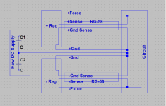
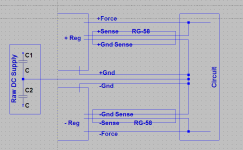
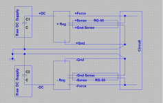
I was looking at Gary Galo's method for connecting super regulators. I've made a drawing based upon his recommendation for connecting your style regulators to the load. Is my drawing the best way to connect the regulators? Or is there a better way?
As always, Thanks.
Ken
I was looking at Gary Galo's method for connecting super regulators. I've made a drawing based upon his recommendation for connecting your style regulators to the load. Is my drawing the best way to connect the regulators? Or is there a better way?
As always, Thanks.
Ken
Attachments
I have been "experimenting" with some pre amps and phono amps and have settled on the ones I'd like make or already have made. The phono will be the 37dB Salas simplistic RIAA as per the pdf, at the moment on breadboard. First I tried it out with a CRCRC+317 to get some kind of a feel, sound was good but there was too much noise so just for fun I tested the V1.2R up to 45V on a breadboard. What a difference, totally silent and the sound is soo much better! The preamp then is a slightly modified version of the cascoded jboz that Juma posted in the Jfet BOZ thread which sounds great. I tried some other versions too but did not like them as much.
As the RIAA sounded that much better with one shunt for 2 channels I was thinking of doing shunts for all the supplies, 2pcs for 40V (preamp), 2pcs 24V for the RIAA and 2pcs for the -3.5V (preamp). I have one transformer 2x40V 150VA and one transformer 2x12V 80VA. For the 40V and 24V I was thinking of using the 150VA 40V transformer and for the -3.5V the 80VA 12V.
Do you think this will be too much for the transformers or too overkill for the application that I am thinking of or do you have any other comments?
Regards,
Mats
Mats, its just down to your aspirations VS investing in time and parts. The law of diminishing returns rears its ugly head at a point. All the difference is at what point you are content. A prudent way is to go step by step and try to stop when differences start to seem like too much complication for nothing to you.
Attachments
Hi Salas,
I see that between the schematics in #4764 and #4287 there is another main change, i.e. a N channel instead of a P ch for M2 - with D and S swapped (as you already did in almost all your shunts). Is there a real advantage in doing this (apart of availability in your drawer") )?
)?
Another question regarding 4-wires connections: if I have one regulator and two circuits to supply (for example 2 channels of a pre), is it correct to wire Force and Sense couples to both the circuits?
Many thanks
Guido
I see that between the schematics in #4764 and #4287 there is another main change, i.e. a N channel instead of a P ch for M2 - with D and S swapped (as you already did in almost all your shunts). Is there a real advantage in doing this (apart of availability in your drawer
)?Another question regarding 4-wires connections: if I have one regulator and two circuits to supply (for example 2 channels of a pre), is it correct to wire Force and Sense couples to both the circuits?
Many thanks
Guido
- Status
- This old topic is closed. If you want to reopen this topic, contact a moderator using the "Report Post" button.
- Home
- Amplifiers
- Power Supplies
- The simplistic Salas low voltage shunt regulator