Now the questions:
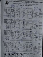
I also attach the schematic for the plan (it's basically yours with a bit of photoshopping, I hope you don't mind)
- Will thermal drift be an issue for such a case above? i.e. temperature will cause change on Q9's current, thus changing the V drop across R11 and in effect making the Vref voltage drifting?
- If it will be a problem, can I revert back to the Vref from the v1.0, using a zener? If so, should I change the value of C1 back into 100uF or keep it at 4.7uF?
- On the case of using zener as Vref, what is the best scenario to put a trimmer to "fine tune" the output voltage (i.e. within 1V), so I can get exactly symmetrical voltage at +/- 12V, is it by using small value trimmer in series with the zener or somewhere else?
- What do you think is the best shunt current to load current ratio? i.e. 180mA through R1 for 80mA shunt current and 100mA load makes it 1:1.25 ratio...
Well, that's it, sorry for the long questions, anyways, you rocks!
In a small box it can be more of an issue but contained enough for just 12V scale. What you can do is to delete the trimmer from the K170's tale, and use a smaller Vref resistor with all the IDSS running, will be less drifty, so not to use Zener and lytic. Zener needs a lytic. That will be better quality wise as it will still be resistor & film cap, since you don't aim to a variable reg. Even smaller drift you will get with a K117GR if you can find. Resistor or Zener you can have a small trimmer in series with the Vref element to be able fix it a bit after equilibrium or for tolerances. 1:1.25 current ratio I use many times in phonos with 1.2R and its fine.
DDDAC to build in 7 Salas regulator
Hi All,
Sorry I post this for the second time")
Spent the last weeks with my DDDAC to build in 7 Salas regulator, connected to 1 Transformer 2x12 volt 500VA with soft start.
The problem is when I connect 3 Salas regulator to the DDDAC receiver board I blow up the diodes on the zero side from 1 Salas regulator
2 Salas regulator works good, after that I connect the third Salas regulator to another 12 volt transformer and everything works fine.
And I must say the sound is really good with only 3 Salas regs on the receiver board.
What is the reason why the diodes blows up from the third one, who give’s the right answer to me?
Salas told me there is no problem to connect 7 Salas regulator to 1 Transformer.
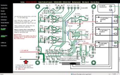
Here you have the schematic how the 5 volt Salas reg is build.
It is weird that de Salas reg perfect works with a second transformer.
I have connect now all 3 Salas regs only the plus output of the Salas reg to the receiver board, and NOT connect the zero to the receiver board because then I blow up de diode again 2N2004
If I measured between the zero of the Salas reg output and GND DAC, I get these values:
Salas reg B -2.15 Volt Receiver board
Salas reg A 5.30 volt Receiver board
Salas reg C 5.30 volt Receiver board
2 off 8.4V 800mA (DAC Tower à 12xTDA1543)
3 off 5V 80mA (Receiver board)
2 off 3.5V 80mA (DAC Tower à 74VHC125N)
2 off 3.3V 80mA (à VDD1 USB Receiver & DAC PCM2707PJT; 74HC08) (à VDD2 Tent XO Clock 12Mhz)
DDDAC1543 mk2: http://www.dddac.de/files/dddac1543mk2ver50.pdf
Reg B I get a minus sign on the meter, which is not good I think.
I take 1 measuring pen on the same place.
I only connect the receiver board, NOT the DAC towers and 12 volt DC.
Regards,
Rudy
Hi All,
Sorry I post this for the second time
Spent the last weeks with my DDDAC to build in 7 Salas regulator, connected to 1 Transformer 2x12 volt 500VA with soft start.
The problem is when I connect 3 Salas regulator to the DDDAC receiver board I blow up the diodes on the zero side from 1 Salas regulator
2 Salas regulator works good, after that I connect the third Salas regulator to another 12 volt transformer and everything works fine.
And I must say the sound is really good with only 3 Salas regs on the receiver board.
What is the reason why the diodes blows up from the third one, who give’s the right answer to me?
Salas told me there is no problem to connect 7 Salas regulator to 1 Transformer.
Here you have the schematic how the 5 volt Salas reg is build.
It is weird that de Salas reg perfect works with a second transformer.
I have connect now all 3 Salas regs only the plus output of the Salas reg to the receiver board, and NOT connect the zero to the receiver board because then I blow up de diode again 2N2004
If I measured between the zero of the Salas reg output and GND DAC, I get these values:
Salas reg B -2.15 Volt Receiver board
Salas reg A 5.30 volt Receiver board
Salas reg C 5.30 volt Receiver board
2 off 8.4V 800mA (DAC Tower à 12xTDA1543)
3 off 5V 80mA (Receiver board)
2 off 3.5V 80mA (DAC Tower à 74VHC125N)
2 off 3.3V 80mA (à VDD1 USB Receiver & DAC PCM2707PJT; 74HC08) (à VDD2 Tent XO Clock 12Mhz)
DDDAC1543 mk2: http://www.dddac.de/files/dddac1543mk2ver50.pdf
Reg B I get a minus sign on the meter, which is not good I think.
I take 1 measuring pen on the same place.
I only connect the receiver board, NOT the DAC towers and 12 volt DC.
Regards,
Rudy
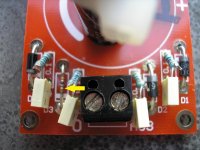
Attachments
I see, that's interesting, I think that's because with the LED there, we can use even smaller resistor value, good point...
You place the LED in between the resistor and JFET right?
Yes. At first, you will still see volatge drop, but eventually the NTC nature of LED will take into place. Therefore, the drop will be restored to certain level. However, there is one problem with this combo.
It is in the Jfet's tale as in the original schematic. Mine is a common blue box vishay 5k VR. In addition, while lowering the Rref, this behavior is more obvious. In fact, I suspect the LED is the cause. The current from jFet is very little, I can only see a tiny bit of light from the core of LED. By the way, I should make it clear. When I mean 'drop' , it is actually the opposite. The output voltage will increase while temperature rises, then the NTC of LED will help to lower the voltage. So, the voltage 'deviation' is at minimum.
Last edited:
Salas,
Have you ever compare your regulator with the flea power regulator (AD797 op-based)? I also heard good things about the later. If there is a noise/freq figure on the 1.2R that would be great.
No, I did not develop it against other regs, but just to suit my requirements on my DIYs. There are much better around technically to consider, made by real engineers. There are the sims which show good noise the bigger the Vref caps go but beyond a simple scope I got which shows a slim noiseless DC line, I have no spectrum analyzer to quote figures. It tackles 60dB gain almost zero PSRR phono stage adequately for noise floor if of any clue vale.
Last time you asked you said with 1N4004 was fine. What happened differently next? Does the bang happen when you connect the negative reg as third in a row, or any polarity?
Hi Salas,
I only replaced the blow up diode 1N4007 with 1N4004.
There is no negative reg, the DDDAC is ony positief
>>What happened differently next?<<
Nothing, first i need 3 Salas regs playing with 1 Transformer, after that total 7 positief Salas regs.
2 off 8.4V 800mA (DAC Tower à 12xTDA1543)
3 off 5V 80mA (Receiver board)
2 off 3.5V 80mA (DAC Tower à 74VHC125N)
I hope i discribe the situation on the best way. Post: #4046
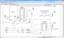
Here you see the schema from receiver board.
Regards,
Rudy
Attachments
Last edited:
First I would test with resistor dummy loads to each reg so to see how many can work in isolation of your supplied circuit. If it still blows a diode then I would see to use heavier diode. If nothing happens and blows only with the specific supplied circuit, I would use more transformers. Those are practical steps.
Thanks for the onfo, I order resistors and I will test it, all regs connected to 1 transformer and connect all the outputs with resistor dummy loads to each reg.
Is 200 ohm for 1 reg the right one?
Regards,
Rudy
Is 200 ohm for 1 reg the right one?
Then I blow up the board, that is happened before.If it still blows a diode then I would see to use heavier diode
Regards,
Rudy
Attachments
- Status
- This old topic is closed. If you want to reopen this topic, contact a moderator using the "Report Post" button.
- Home
- Amplifiers
- Power Supplies
- The simplistic Salas low voltage shunt regulator