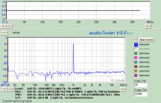
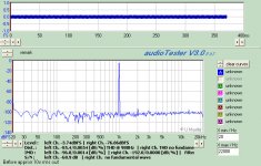
I haven't attacked the voltage rise yet, rather jumped ahead and hooked this bad boy up. The whole point was to drive an LME49811 driving a modified Allison configuration current amp output. The 49811 is driven at 60v, the output stage is driven at 32v. The before and after results tell the story.
The before was with the 49811 driven off the same 32v supply through 20ohm resistors and a boat load of MKP and litic decoupling caps.
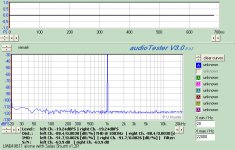
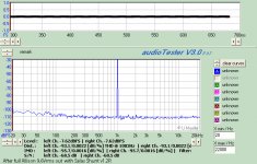
The after show two different outputs the 49811 terminated into 100ohm resistors and no decoupling caps. The second after image is the full amp at 9.6v rms out into 8 ohms.
How does it sound. More bass, better attack, very, very nice.
Ken
The before was with the 49811 driven off the same 32v supply through 20ohm resistors and a boat load of MKP and litic decoupling caps.
The after show two different outputs the 49811 terminated into 100ohm resistors and no decoupling caps. The second after image is the full amp at 9.6v rms out into 8 ohms.
How does it sound. More bass, better attack, very, very nice.
Ken
Attachments
10dB lower noise floor on the PSU alone? Do I get it right? What is the PSRR? Does it compute? I had reports that op amps are also subjectively affected by the reg, especially in dynamics and smoothness, it seems that the trend continues in this is larger scale chip too.
*I am worried about the heat on the BC546-556 error amp BJTs at 60V also. Can they get a TO-92 sink?
*I am worried about the heat on the BC546-556 error amp BJTs at 60V also. Can they get a TO-92 sink?
10dB lower noise floor on the PSU alone? Do I get it right? What is the PSRR? Does it compute? I had reports that op amps are also subjectively affected by the reg, especially in dynamics and smoothness, it seems that the trend continues in this is larger scale chip too.
*I am worried about the heat on the BC546-556 error amp BJTs at 60V also. Can they get a TO-92 sink?
Salas,
My test setup procedures are relatively consistent, I have been able to return and re-test with consistent results. Though this time my original front end did not re-test well at all. It's been in use for 6mnths or so in an open shop environment and has degraded in performance somewhat. That said, I believe these test results. Before the shunt implementation, I was pretty proud of the performance of the chip and the entire amp and had been able to consistently get the results shown in the before shunt graph.
I'm attributing these results to the complete isolation of the VAS stage (the LME49811) power supply from the output stage power supply with it's large current swings. I expected good results from the shunt implementation, but these results are more than expected.
The application notes for the chip place a lot of emphasis on proper bypass of the power supply, recommending a combination of film and litic caps both as the power comes to the board and also at the chip itself. Along with these recommendation they also recommended separate power wires from the supply caps to the chip and to the output section of the amp. All these recommendation suggest that the chip is sensitive to the implementation of the power supply.
As this is still a prototype, I will definitely include a heat sink for the error amp bjt in the final version.
Again, thank you for all your kind words and help.
Ken
hi guys, well I just powered up a V1 QH board for the first time, 15vac raw supply input, IRF9520/540 fets, green LEDs and 4R for R1. using a trimmer to set Vout for now and sense lines shorted with only 150R resistor load across the output. CREE zero rec to220 diodes. everything lights up fine and Vout adjustment works as expected (set to 12vdc), but current is through the roof at 870-900ma!! I expected MUCH less than this and my Q1 heatsink isnt up to the task so I turned it off. any ideas? you guys wanna see pics? could oscillation cause this? or perhaps the diodes are causing issues?
Salas,
Well, your suspicions were right, a bit to good to be true. I'm using Pete Millets sound card interface. When the range is set to 20v, it jumps the scale up by approx. 10db. So the measurements were not taking at the same range settings. I got the non-shunt chip running well again, (the input wires were a bit tired) and it measures close to the shunt version. More later.
Ken
Well, your suspicions were right, a bit to good to be true.
I'm using Pete Millets sound card interface. When the range is set to 20v, it jumps the scale up by approx. 10db. So the measurements were not taking at the same range settings. I got the non-shunt chip running well again, (the input wires were a bit tired) and it measures close to the shunt version. More later.Ken
hi guys, well I just powered up a V1 QH board for the first time, 15vac raw supply input, IRF9520/540 fets, green LEDs and 4R for R1. using a trimmer to set Vout for now and sense lines shorted with only 150R resistor load across the output. CREE zero rec to220 diodes. everything lights up fine and Vout adjustment works as expected (set to 12vdc), but current is through the roof at 870-900ma!! I expected MUCH less than this and my Q1 heatsink isnt up to the task so I turned it off. any ideas? you guys wanna see pics? could oscillation cause this? or perhaps the diodes are causing issues?
Use 10R R1 to drop it. 4R is for high current, especially if the leds are over 2V it picks up current setting easily. Also use 18VDC raw for 12V out. 3V drop is not good for this reg, although it may work somehow.
Salas,
Well, your suspicions were right, a bit to good to be true.
Ken
It can be subjectively better because of other parameters in the reg, or bit cleaner FFT, but the straight 10dB difference was suspicious to me with such PSRR chip.
Use 10R R1 to drop it. 4R is for high current, especially if the leds are over 2V it picks up current setting easily. Also use 18VDC raw for 12V out. 3V drop is not good for this reg, although it may work somehow.
huh? posts I read in here and the GB thread put 10R at 63ma, I need a 150-200ma, just dont need nearly 1A, which is a bit jump from 63ma with only changing 10R to 4R. 12v is just an arbitrary number I picked for testing, I have no purpose for the reg just yet, 15VAC IS raw >18VDC is it not? thought I was pretty covered there. somewhere needs to be a definitive current setting table, I have read 3 very different advices on current setting for R1 so far for the same version reg.
thanks for your help
Last edited:
a formula for working out current setting myself for the V1 reg would of course be better; I searched the threads and did not come up wiyth anything definitive except for some posts by andrew T, which were apparently inaccurate, as his was what gave me the 10R = 63ma number
No, I did not. Who told you they were inaccurate? Did you try to find what was wrong? Did you ask before using an apparently wrong formula?a formula for working out current setting myself for the V1 reg would of course be better; I searched the threads and did not come up with anything definitive except for some posts by Andrew T., which were apparently inaccurate, as his was what gave me the 10R = 63ma number
The voltage across the current setting resistor is ~1.4V to 2.4V depending on LED Vf and FET Vgs.
You must measure this voltage if you want a fairly precise CCS current.
Use Ohm's law to calculate the required resistor value.
I = V / R rearranged to bring R to the left hand side.
R = V / I
If Vr1 = 1.6V
and Iccs = 200mA = 0.2A
then R = 1.6 / 0.2 = 8r0.
This method of calculating the required resistor value has been repeated many times in the various Salas Shunt reg threads.
I further have recommended that the builder fits a resistor of roughly double the value for the required CCS current. Then measures the actual Vr1 and finds the actual CCS current. Then find what extra current is required to achieve the desired Total CCS current. Now using the measured Vr1 and the extra current calculate the parallel resistor required and add it in parallel to the existing double value resistor used for the first build.
I have stated this in at least two previous posts.
Last edited:
your trust is misplaced. I am only now learning about why and how TMC operates.Knowing Andrew's thoroughness, I highly doubt he gave inaccurate info. There must have been a misunderstanding. I would actually trust Andrew to calculate TMC compensation for V1.2 only with pen and paper.
But, to some extent your statement follows my philosophy: one must understand the operation and be able to check that the software is correct before one can come to rely on the predictions to the questions asked of the software, i.e. the pencil and the back of an envelope must come first. But there again quite a high proportion in this Forum disagree with me, on this and many other views I hold.
No, I did not. Who told you they were inaccurate? Did you try to find what was wrong? Did you ask before using an apparently wrong formula?
The voltage across the current setting resistor is ~1.4V to 2.4V depending on LED Vf and FET Vgs.
You must measure this voltage if you want a fairly precise CCS current.
Use Ohm's law to calculate the required resistor value.
I = V / R rearranged to bring R to the left hand side.
R = V / I
If Vr1 = 1.6V
and Iccs = 200mA = 0.2A
then R = 1.6 / 0.2 = 8r0.
This method of calculating the required resistor value has been repeated many times in the various Salas Shunt reg threads.
I further have recommended that the builder fits a resistor of roughly double the value for the required CCS current. Then measures the actual Vr1 and finds the actual CCS current. Then find what extra current is required to achieve the desired Total CCS current. Now using the measured Vr1 and the extra current calculate the parallel resistor required and add it in parallel to the existing double value resistor used for the first build.
I have stated this in at least two previous posts.
no, what I was saying was that the only seemingly definitive posts I found on current setting with this particular QH V1 PCB were in the GB thread and 10R for 63ma was mentioned along with 2 or 3 other values. perhaps I misunderstood, or you were referring to something else. i'll try and find it a bit later on. changed to 10R and still way too high, so something else is up. got 470ma and at that current with my sink I wasnt about to let it stabilize. I only built this reg to cope with 150-200ma, so only using fairly small onboard sinks (1.5" and 1")
another thing that I havent experienced with other regs is that using a meter to check the current on the output of this reg appears to actually load the reg to the point the LED bypassing the trimmer goes out. i've only had this fluke for a couple days (Fluke 111) but its not rocket science, its on DC current setting.
thanks very much for the above, there is so much posted on this subject and so many different versions of the design and each of those vary with the components choice and personality of the builder. I stuck to recommended values for everything on this one, as wanted to get my head around the behavior before I changed anything.
Salas said:The formula is (LEDSstringVdrop-VGSofCCSMOSFET)/Rset. Input voltage to reg is raw DC from bridge & cap. 6V Input to output is good, 10V is better.
perfect thanks, i'm thinking MY LED string vf is too high, combined with a low vgs mosfet; i'm not 100% certain the LEDs are all from the same batch with the same rating. so will measure the actual VF in a moment.
if Qusp DMM is set to current (ammeter) then it effectively shorts the output and the supply rail voltage will drop to near zero and the Vref LED/s will go out.
Qusp,
Where does it say 10r and 63mA?
I seem to recall the original 63mA could be obtained by paralleling two 68r for an effective 34r as the CCS current setting value.
Qusp,
Where does it say 10r and 63mA?
I seem to recall the original 63mA could be obtained by paralleling two 68r for an effective 34r as the CCS current setting value.
nah i've got 150R across the output as dummy load for load testing and also so the output isnt just open, but how else can I measure current than from one side of it to ground? ie in series
I had wondered about oscillations, but dont have a scope and dont have the time to be screwing around with the current this high until I get it set up with more effective heatsinking.
when I first switched it on I had the trimmer down quite low by accident as I had turned it down to find the beginning of the range and then turned it back about 4-5 turns (25 turn pot), and that was before I had measured current, so it could have been set VERY low and with VERY high current could have killed something one of the jfets perhaps??but other than this current issue everything seems to act as normal, all LEDs on, Vout adjustment responds immediately. Q1 hardly breaks a sweat, only Q6 is toasty.
@ Andrew
i'll go see if I can find the post now, it had 3 or 4 resistor values for R1 and its associated current. I hope it really was you and not just my memory playing tricks as I had read a number of your posts.
Last edited:
You should put the DMM in series with the 150R in current mode. Across output only in voltage mode. Else its a dead short. If there is enough inductance from the DMM leads in series with the dummy load it can be upsetting it. What voltage is across the 150R (12V?) should represent a V/R current trough it anyway. Set it for 150-200mA given your leds and Vgs, see if it misbehaves at all, and restore any hit component if so. (Could be had something stressed during the initial tests, rather not). I trust you will tackle setting it easily. Its not too difficult. Some guy from all those who got such boards should open a builders thread IMHO by the way. Its a bit specific topic to a certain layout and settings. V1 reg is not something new to elaborate for ever here. It certainly have worked OK for hundreds of builds in different guises by now.
- Status
- This old topic is closed. If you want to reopen this topic, contact a moderator using the "Report Post" button.
- Home
- Amplifiers
- Power Supplies
- The simplistic Salas low voltage shunt regulator