I would like to see, in the higher voltage versions, where a resistor is used to set up the voltage reference, a three component string consisting of resistor, LED and Zener.
For low voltage the Zener is optionally replaced with a diode and the resistor can optional be linked out. The LED shows it's working as well as giving us the low noise, low impedance reference voltage that we need.
How about a proposed V1.0a and V1.2a with these modifications?
Zener is difficult to find with good noise in reality if not a special Tc compensated component, got to be purchased in volume. After having seen many doing bad or good enough, but erratically so, I would not recommend different than (easily available) LM329 6.9V and multiple use of it. Unfortunately the nice pp cap viable for the Norton ref should be augmented by at least 100uF chemical cap //. The Norton ref is nice for higher voltage, gives a nice variable Vout with the trimmer, if someone wishes minimal voltage slide till Jfet's Tc comparable to active ref elements, it can be made small value, lytic filtered, and use the fet ccs in its tail g&s shorted. Although better current than what with a typical 20-27k Norton at say 20V-30V range looks nice for the base needs of the BJT error amp, Spice shows no appreciable dynamic improvement beyond 0.2mA availability. Its a matter of choice the Vref and its subjective evaluation, variability on the fly or not priorities, bypass features, for the connoisseur builder.
P.S. 1.0 was always made with active elements too. Remember DCB1, several low voltage, and phono realizations.
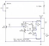
Avoid Schottky diodes in the Vref (1A to go 0.6V)... Nice then (horosho?), please post the total final well working cct for any guy's reference who will be interested in a tested 1.2(ish) based 3.3V solution in the future. We like pictures too.")
P.S. You mentioned that you had 1.0 based regs there before, correct? Now its a 1.2 5V all Mosfet and the 3.3V with a BD140 in the shunt position we ended up with, right? Was there remote sensing implemented for the 1.0s too? Can you differentiate the before and after regs subjectively?
Final circuit is attached. Yes, before I was using V1.0 regs without remote sensing, now the config is just like you said.
I really can't remember how it was sounding with original LM317 regs, but I will try to describe the differences between v1.0 and v1.2 :
- first thing that I noticed was the bass, it became more tighter and kind of deeper;
- scene has widened, don't know if it's the right term, you know, kind of 3D effect;
- more microdetails revealed, I guess that's because of lowering of the noise floor;
- highs gained more definition, and, became even more clearer (after latest changes in 3.3V reg).
I guess that's it, I'm sure there's more changes than that, just that I can't put them to words.
P.S. Now I will remember that different kinds of diodes should be used in different applications
P.P.S. Horosho - is correct
Thanks,
Fedor
Attachments
Thanks for the detailed info. Looks like the digital circuits are quite susceptible since you can give such a clear subjective account between shunt reg versions on them. Is it a Gigaworks platform? I guess you use a 10uF and 0.5R output Zobel in practice, but in this one since the Cdom is high and there's no buffer even the 2u2 & 1R shown might be equivalent or a bit better.
Yes, you are right, it's Gigaworks DAC. I'm using 10uF and 0.5R Zobel only on one of 5V regs (changed from 4u7 and 1R when I saw some oscillation on the scope), other 5V and 3V3 are using 4u7 and 1R. Sorry, I didn't corrected it on the schematic. So it may be better to change to 2u2?
Last edited:
Depending on the load interaction, the smallest you can go without oscillation traces, the better. Since we don't know if other builders will have oscopes, I will edit that picture to 10uF+0.5R to be sure of what we have tested in the most difficult situation. The one that gave you a bit of oscillation from those with 4u7+1R and you changed it, was on a very different circuit feed?
The one with oscillation was feeding two devices actually - SPDIF reciever chip (CS8416) and ASRC chip (CS8421) with clock crystal. While the other one was only for DAC chip (CS4398), so I guess two devices with their surrounding elements can produce some oscillation for certain Zobel network. Yes, you are right about the schematics, so not to confuse future builders.
Thank you for your great work and support
Thank you for your great work and support
A pleasure. Hey, where are your pictures showing so many regs and so many digital chips? I was listening to the Gigaworks just yesterday with Lundahl outputs and normal regs VS the Audiodesign with my LV 1.0 & HV regs, a friend here made both. He was curious if the Giga will match the 3D and body of the rather less airy NOS DAC and valves I/V one, if with same regs. But one was like 2D compared to the other for now. He says its the supplies he can recognize a lot though. Maybe he has to fly to UKR for a quick comparison so not to be making regs for the Giga if it will not go the same way.
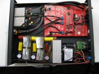
Here it is I was little embarassed to upload the pic of my build, because of ugly heatsinks Those are handmade from CPU cooler. I plan to change them to something more presentable in the future Well, this is basically my first and only DAC for now, so can't say how it may compare to others. Your regs are definetely good for the sound, and added lots of 3D The transformers on the output is UTC A-20.
I was little embarassed to upload the pic of my build, because of ugly heatsinks Those are handmade from CPU cooler. I plan to change them to something more presentable in the future Well, this is basically my first and only DAC for now, so can't say how it may compare to others. Your regs are definetely good for the sound, and added lots of 3D The transformers on the output is UTC A-20.Attachments
Here it is
Surely shows the way towards my friend's aspirations for regs. Nice one.
P.S. I don't wanna hear about presentational looks, essence counts. I see nice coax for sense, especially good in a digital environment. Congratulations.
The one with oscillation was feeding two devices actually - SPDIF reciever chip (CS8416) and ASRC chip (CS8421) with clock crystal. While the other one was only for DAC chip (CS4398), so I guess two devices with their surrounding elements can produce some oscillation for certain Zobel network. Yes, you are right about the schematics, so not to confuse future builders.
Thank you for your great work and support
At Mhz speed shunt regs are "out of steam"
Your best friends there are capacitors
Will not match the cascoded tail main CCS's PSRR. Even if with cascoded depletions.
All depends on your design priority, there is no free lunch
Somethimes you need to sacrifice some dB rejection for wider bandwith and linearity. Think about IRFP9240 capacitance & what circuits will be feed with 3.3V. There is no need to feed cleanest possible DC to those circuits. More important is to isolate them from interfering with each other. Even simple NPN transistor at supply pin will provide additional ~40dB rejection.
Yeah, there is different priority for phono stage & higher voltage shunt regs than for those circuits & 5v or 3.3V shunt regs

Last edited:
The CCS's cascode tail takes care of that gate. It widens the PSRR's bandwidth. You can use IRF9610 for main CCS position too no problem, I have specified and tested that also right from the start in page 190, better, but not as much as in raw VS more capacitive Mosfets. Anyway, those regs aren't made with digital in mind. If they manage to sound better to people than some others in digital too, all well. If not, mod them or use specific for digital.
Surely shows the way towards my friend's aspirations for regs. Nice one.
P.S. I don't wanna hear about presentational looks, essence counts. I see nice coax for sense, especially good in a digital environment. Congratulations.
Thank you
The coax is Soviet, made with some white metal, hardly it's silver, maybe nickel, or something.At Mhz speed shunt regs are "out of steam"
Your best friends there are capacitors
You mean capacitors on the output, in the Zobel network?
fred_com said:You mean capacitors on the output, in the Zobel network?
Capacitors at power supply pins.
Salas said:Anyway, those regs aren't made with digital in mind. If they manage to sound better to people than some others in digital too, all well. If not, mod them or use specific for digital.
Yeah, they can be modded in different ways, I just posted one way. Removed your copyright notice "Salas 2009-2010" that nobody can associate you with my bad design
Its not bad and its not a heavy redesign, its only changing the main CCS for minimum parts count still with low capacitance, and much acceptably so. I would prefer the 9610 with a cascode on its gate, that's all. What happened with that 3V3 dedicated one you did with Iko? Tested it?
that 3.3V evolved further with parts count reduced to minimum. Learned hard way that more important than single super regulator is local bypass for each chip and to "isolate" each chip to prevent him from interfereing with other chips. For "digital" chips.
Why I choose DN2540? According to Walt Jung measurements & measurements from others, this simple depletion device will give you over 100dB rejection over whole audio band. Just a single device + 2 resistors. Even if shunt MOSFET or transistor not working, there is over 100dB rejection. At 200kHz still 90dB rejection.
No need for overengenering if input voltage ripple is bellow 1V
Do you compensate for stability at the output, or with lead lag internal, or with both?
P.S. Have done once that page 4 one in the link for tube anode CCS. Hiss went up so much I went back to a resistor. Also DN2540's 150mA Idss is not always enough here. We routinely run over 200mA.
P.S. Have done once that page 4 one in the link for tube anode CCS. Hiss went up so much I went back to a resistor. Also DN2540's 150mA Idss is not always enough here. We routinely run over 200mA.
- Status
- This old topic is closed. If you want to reopen this topic, contact a moderator using the "Report Post" button.
- Home
- Amplifiers
- Power Supplies
- The simplistic Salas low voltage shunt regulator