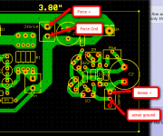
C4 is still too close Q4 IMHO. You haven't space to mount a heatsink.
Move the CCS components a bit on the left and C4 & Jforce down to the center of the board, between Rj (but leave space as they generate heat) and Q2a
Massimo,
Thanks, will do.
Ken
Hi Ken
Are you using a zenner for vref ?
IMO you should try to place the outputs closer together so sense wiring will be easier to implement 🙂
Are you using a zenner for vref ?
IMO you should try to place the outputs closer together so sense wiring will be easier to implement 🙂
Hi, here's the schematic I use for heating direct heated triode filaments. It works very stable at 1A and more, output ripple is in mV range. You can use my layout or make your own, raster is 2.54mm. Make sure you use thick conductors if currents are exceeding 250mA.
Thanks Nick, it's a good job you did on this one!
Any impressions on this versus CCS for DHT?
Hi Ken
Are you using a zenner for vref ?
IMO you should try to place the outputs closer together so sense wiring will be easier to implement 🙂
Hi RCruz,
I'm going to try it both ways - with zenner or resistor/pot to set voltage. I'm less sure what you mean about putting the outputs closer together. As I understand it, the output - Force is a pair of wires, and the sense is a seperate shielded pair probably coax. Am I miss understanding something?
Ken
There are two sense wires (+ and -) that should be shielded so the correspondent outputs should be close.
I have a similar layout and my problem is to connect inner core of shield to sense + and the shield to sense - because my outputs are 2cm apart.
I have a similar layout and my problem is to connect inner core of shield to sense + and the shield to sense - because my outputs are 2cm apart.
There are two sense wires (+ and -) that should be shielded so the correspondent outputs should be close.
I have a similar layout and my problem is to connect inner core of shield to sense + and the shield to sense - because my outputs are 2cm apart.
Here is how I think it gets hooked up.
Ken
Attachments
Will be better to connect Rs directly at the load togheter the reg cable + with force & gnd with sense & all shield wire togheter at gnd only in the reg side?
Boh shielda only be connected to reg. gnd ok?
An externally hosted image should be here but it was not working when we last tested it.
Boh shielda only be connected to reg. gnd ok?
Last edited:
Merlin, from the shunt reg "force out" to RIAA "load in" use a pair of the tickest single cable (1.5 - 2 mm) you have handy and then, directly to "load in", use a shielded cable from "sense in".
It goes without saying that the Vref components aren't connected to the "force out + and -" anywhere, but at "load in".
This is the only working configuration. The sketch you drawn makes no sense.
It goes without saying that the Vref components aren't connected to the "force out + and -" anywhere, but at "load in".
This is the only working configuration. The sketch you drawn makes no sense.
I thinks is more clear in this new image:
An externally hosted image should be here but it was not working when we last tested it.
Read what I wrote above.
In other words, from "load in + and -" on the RIAA board run a pair of thick single cables (+ and -) to Reg out "force + and -" and from the same pads, a shielded cable to "sense in" where the outer conductor obviously connected to " - " and the inner one to " + "
In other words, from "load in + and -" on the RIAA board run a pair of thick single cables (+ and -) to Reg out "force + and -" and from the same pads, a shielded cable to "sense in" where the outer conductor obviously connected to " - " and the inner one to " + "
Like this picture:
Or only the + positive for sense?
An externally hosted image should be here but it was not working when we last tested it.
Or only the + positive for sense?
Last edited:
For one channel, you can use just one coax cable. One the regulator side the inner wire of the coax is connected to sense+, the sleeve of the coax is connected to sense-; on the load side, your riaa, the inner wire of the coax is connected to the point where the thick force+ wire is connected. The sleeve of the coax is connected to where the force- wire is connected. Hope this helps.
The shield of the coax for sense is connected on the shunt sense (-) and also at the riaa (-)
Like this Iko / Rcruz:
An externally hosted image should be here but it was not working when we last tested it.
Yes. Make sure the force wires connect at the same point on the riaa (load) as the sense wires. Best is to have very very short force wires.
¡Hola Felipe! Muy bien.
La prossima volta scrivo in italiano così capisci meglio 😉
(Next time I write in Italian so you can understand)
La prossima volta scrivo in italiano così capisci meglio 😉
(Next time I write in Italian so you can understand)
@massimo
Grazie, puoi scrivere in italiano per pm per me sarebe meglio e piu facile di capire.
@Rcruz
Muito obrigado por tua ajuda.
@Iko
Thank you, your post be like a light in the night.
Nothing like good friends to help me, I'm proud to be in this forum.
Grazie, puoi scrivere in italiano per pm per me sarebe meglio e piu facile di capire.
@Rcruz
Muito obrigado por tua ajuda.
@Iko
Thank you, your post be like a light in the night.
Nothing like good friends to help me, I'm proud to be in this forum.
Last edited:
I am thinking if the isolated heatsinks should be grounded. In that case the heatsinks also serve as EMI shield for the MOSFETs and the circuit board.
On second thought, use R1 = 22R or 15R 2-5W for 140-190mA its more conservative at 40-50V area for dissipation. Its the same circuit slightly better set for heat.
I see more changes between mine Shunt Reg. PSU & Rs:
Shunt
R2 330
R3 10
R5 220
R6 4K7+4K7trimmer
R8 33K
Rs
R2 220
R3 1
R5 270
R6 4K7+5Ktrimmer
R8 27K
I have to change these resistors and put the values for Rs?
Last edited:
- Status
- Not open for further replies.
- Home
- Amplifiers
- Power Supplies
- The simplistic Salas low voltage shunt regulator