Earl, thanks for jumping in. Is there any way to calculate this out using your method in such a way that anyone would be able to identify a relative error at different points with different drivers? If not, is my approach within a reasonable error range? If not, any suggestions as to how I might make it so?
Jay
Thats a good question, but I am not sure how one would do that, or if it even makes sense. The reason is that I would expect the "errors" to be different for every case, thus making a simple approach kind of meanigless. I might try and do a far field plot and then show what the plot looks like using the nearfield data that would show the errors for that case, but I don't think that you could generalize the situation.
For example, the monopole mode has a very short nearfield and basically any measurement of it is a good measurement. On the other side is the 16th mode which will have a very long nearfield and one needs to be fairly far away to get good far field accuracy (if you don;t do what I do) of this one. So it is easy to presume that a very wide directivity speaker would be easier to measure at close distances than one with a very high directivity. This simple example does not seem to fall out from what you are showing or discussing since the errors do not seem to depend on the sources directivity and they will.
Thanks for the curves Bolserst. Of course this does remind us of why we don't use 12" woofers to 57,000 Hz!
These look similar to my line array simulations except mine showed the periodic wiggles and a 3dB per doubling slope since I was approaching a line rather than a plane.
Still, I think a ka of 5, or at most 10 is as high as we would go with any radiator (multiway assumed), and at those frequencies the low frequency curve isn't far off.
David
...so this all begs the question, "how much error are we experiencing (realizing that each is a case specific situation) when we measure drivers or loudspeaker systems at 1 meter?"
The directivity issue also seems to address my concern earlier about the enclosure dimensions not necessarily contributing as much to the signature as the actual driver.
Jay
The directivity issue also seems to address my concern earlier about the enclosure dimensions not necessarily contributing as much to the signature as the actual driver.
Jay
I know from experience that medium or small sized systems, if you pick the axis carefully, can be measured at 1meter with reasonable accuracy. There is a very real trade off with farther distances meaning more room effect, more anechoic chamber contribution (at LF), or a smaller time window for gated measurements, fighting against any potential near field inaccuracy.
David S.
David S.
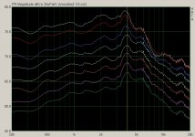
OK, so I decided to do a very rough experiment. I measured a loudspeaker in an enclosure at varying distances and calculated the anticipated drop from each distance to the next if we were to be in the farfield (20*LOG(Distance a/Distance b)). I compared this to the actual drop measured. This was done with a calibrated mic and data below about 350 hz is windowed out but there are some visible patterns. In addition, the measurement distance has an innate error as it is measured to the baffle and not to the acoustic center (wherever that truly is ). Additional information includes: The diameter of the woofer including the surround: 15.1 cm; without the surround; 12 cm; The enclosure is 20.7 cm by 34 cm; The tweeter is 2.3 cm in diameter to the outside of the surround and 1.9 cm on the inside of the surround though it is behind a waveguide. Both drivers are centered on the baffle with the top of the tweeter 6 cm and the top of the woofer 12.7 cm from the top of the baffle.
Admittedly, this is a crude experiment and I did not measure beyond 112 cm. In addition, this is a two driver system with a crossover in place so it will also impact things (I did not take the time this morning to disconnect one driver, that will be my next experiment)...but this does show some interesting information, regardless. Certainly, the degree of error is minimal by the time one gets to a meter away.
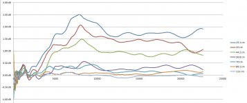
Attached are the actual measurement curves and then a graph of the error at each measurement distance.
For some reason, I can only upload one file at a time. I will upload the measurement error in the next reply.
Jay
). Additional information includes: The diameter of the woofer including the surround: 15.1 cm; without the surround; 12 cm; The enclosure is 20.7 cm by 34 cm; The tweeter is 2.3 cm in diameter to the outside of the surround and 1.9 cm on the inside of the surround though it is behind a waveguide. Both drivers are centered on the baffle with the top of the tweeter 6 cm and the top of the woofer 12.7 cm from the top of the baffle.Admittedly, this is a crude experiment and I did not measure beyond 112 cm. In addition, this is a two driver system with a crossover in place so it will also impact things (I did not take the time this morning to disconnect one driver, that will be my next experiment)...but this does show some interesting information, regardless. Certainly, the degree of error is minimal by the time one gets to a meter away.
Attached are the actual measurement curves and then a graph of the error at each measurement distance.
For some reason, I can only upload one file at a time. I will upload the measurement error in the next reply.
Jay
Attachments
Your curve progression looks exactly as we would expect. The LF varies because the farther curves include the 4pi to 2pi transition, the nearer curves simply show the 2pi response (see Keele) Plus the nearest curves start to show the high ka effects at high frequencies.
Science works!
Where is the acoustic center? As a circular arguement you could define it as the depth location that makes the nearfield draw away curve follow the ideal. (As you get closer, every 6.02dB rise must be cutting the distance to somewhere in half.
David S.
Science works!
Where is the acoustic center? As a circular arguement you could define it as the depth location that makes the nearfield draw away curve follow the ideal. (As you get closer, every 6.02dB rise must be cutting the distance to somewhere in half.
David S.
The original curves were done when I started thinking this through. I have been building and measuring speakers for about a decade now and had just blindly followed the 1 meter rule but never really understood it. As I began to look into it, I found that there were many definitions of farfield and that there seem to be many approximations (that are often promoted as definitions). As an ex-Medical researcher and now clinician, I am generally hesitent to accept research that I do not or cannot understand how they got from point A to point B. I am hoping that others who might see this thread will also ask questions and learn as I have along the way. It is evident that there is more to understanding farfield than meets the eye; Earl's take on it suggests that there are inaccuracies in our estimations and perhaps his method is more exacting (only time and scrutiny will tell) but for now, I think that some guidance can be found in this thread.
One final evaluation that I plan to do is to compare the error identified in my measurements to the spreadsheet at higher frequencies. I expect to see some discrepancies due to the measurements not being from the Acoustic Center and also due to the woofer influences on the tweeter, particularly closer to the xover point. But looking a couple of octaves above the crossover, I anticipate a fairly close correlation. I will report here after I examine the data.
Thanks, Jay
Hi JMB
How much error you get (and how important is it) at one meter depends on the frequency, cabinet size and design as well as what you want to do with the data.
The link I posted earlier is one set of criteria which is based on collecting data for a model of the speakers 3d radiation model, which is then used in EASE and other programs to predict far field behavior in room acoustics / design. It is from an independent acoustic measurement company we hire to measure our cabinets at work partly because I can’t take full spherical measurements and don’t have a very large indoor space to measure in. Measuring every 2.5 or 5 degrees around a sphere is not the definition of a fun time, those guys have a robotic system to do it. In the case of a speaker like an SH-50 with a 28 inch square mouth, I believe they measured at 7 .4 meters mic to source distance. That may be in part due to the source of radiation being a few inches forward of the cabinet’s rear wall and not right behind the grill.
As “everything gets worse” the larger the room and greater the distance from the source, that level of concern may be totally UN-necessary in the home but doing it that way gives measured results in the far field which closely match the predictions (real important in commercial sound).
Best,
Tom
Thanks for the curves Bolserst. Of course this does remind us of why we don't use 12" woofers to 57,000 Hz!
Still, I think a ka of 5, or at most 10 is as high as we would go with any radiator (multiway assumed), and at those frequencies the low frequency curve isn't far off.
Ha! 57kHz
Yeah, the higher ka curves are really only relevent for line arrays of small drivers or ESLs where bigger dimensions are involved.
I'd agree that ka < 10 for single cone drivers in multiway is a pretty safe bet.
Attached are the actual measurement curves and then a graph of the error at each measurement distance.
Hello JMB,
Thanks for posting your measurements. What type of woofer was used?
You might also consider trying a metal cone unit where the cone motion remains pistonic to a higher frequency.
It would probably require a more distant measuring position to minimize measurement errors.
Can you clarify how you calculated the data shown in your error plot?
Were the 7 curves in the error plot calculated from the 8 curves in the measurement plot?
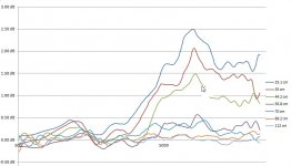
Any chance you can repost the error plot with LOG frequency scale.
Hi bolserst,
I am attaching the log scale of the errors. The 7 error curves are based upon the 8 measurement plots. This was made by graphing relative frd measurements and then subtracting each progressively further measurement. This dB difference was then compared to 20*LOG(one distance/the 2nd distance). The woofer is Polypropylene.
Jay
Attachments
As I re-read some of the posts, it became apparent to me that the AES requirement #2 (see my first post) did not take into account beaming. In addition, as I looked at my tests, it seemed as though they underestimated the error in mid frequencies. I used a Bessel function to calculate off axis energy and found that a decreasing portion of the energy would actually be reflected by the baffle as frequencies increase due to beaming. I then calculated a relative baffle contribution based upon the pct of energy going to the baffle. The equiv baffle is then calculated based upon this vs. the driver source size regarding degree of contribution.
When I compare this new spreadsheet to my findings and to those of Joe D'Appolito's example of farfield (I think page 61) in his book, it seems to be more in line. Please play with this spreadsheet, test it against real world examples, and see what you think. This is a learning endeavor and I welcome comments and guidance.
Thanks,
Jay
Attachments
Hi Jay
While I myself am not too concerned with this problem - for reasons that I stated earlier - I commend your using a strongly analytical approach.
Does your analysis consider true nearfield effects or is it based on the simplified model of radiation usually used? By this I mean that in the Rayleigh integral it is common to assume that the denominator of the Green's function is falrly stationary and that the phase effects occur dominately in the complex exponential in the numerator. This assumption leads to the Bessel function solution that you imply is used here, but it is in error at very small r/a values where this assumption does not hold. This is shown in Kinsler and Frey for example.
Hi Earl,
I thank you so much for your interest. I think that the easiest thing to do is to show you my work. I would be happy to PM you an unlocked spreadsheet, if you would be willing to look at it. I could also unhide the hidden columns and rows (that I hid only for viewing purposes).
Also, I am uploading a corrected version and I apologize for any confusion. My off axis calculations were done in imperial formulas and I had not accurately converted them to metric. In addition, I used a radius of the baffle and not the baffle size. Please use the 1.023 version.
Thanks,
Jay
Attachments
Last edited:
You can send me the Excel sheet if you want and I will try and look at it, but Excell is not my forte. Basically its an easy question to answer - do you use a Bessel function solution or do a full numerical integration? I am suspecting that in Excel you would be limited to using the Bessel function.
Thanks, Earl, and you are right, I do not do the full integration. I use the Excel Bessel function. It had generally been close to target for me when I set this up as an independent spreadsheet to just look at off axis measurements a few years ago, realizing many of its limitations.
Jay
Jay
If you look at the derivation of the Bessel function in this example, it assumes that the location is not too close to the source such that the "(r-r0)^2" in the denominator of the Green's function can just be replaced by r^2, which is true if r >> ro. Its not true near the piston however.
Again, my approach uses functions that are exact right down to the surface of an assumed spherical source - but otherwise there are no approximations. The fact is that there is always a spherical source that will yield the measured results, and it is unique, so this assumption is not a big issue until one gets "within" the assumed source size. The only assumption is that the assumed sphere encompass the real source(s) (again, this is NAH stuff.) If I reconstruct the source velocity that created the measured field, I get it on this assumed sphere, which is not exactly the same as the actual source (unless I arrange it to be). This is usually only a matter of inches so it is pretty accurate. I can actually see cabinet diffraction in the reconstructed velocity data.
Again, my approach uses functions that are exact right down to the surface of an assumed spherical source - but otherwise there are no approximations. The fact is that there is always a spherical source that will yield the measured results, and it is unique, so this assumption is not a big issue until one gets "within" the assumed source size. The only assumption is that the assumed sphere encompass the real source(s) (again, this is NAH stuff.) If I reconstruct the source velocity that created the measured field, I get it on this assumed sphere, which is not exactly the same as the actual source (unless I arrange it to be). This is usually only a matter of inches so it is pretty accurate. I can actually see cabinet diffraction in the reconstructed velocity data.
Last edited:
I can see where the error closer to the source would be an issue but I would think that since we are looking at r>>ro, if I am understanding you correctly, this would not be a problem with this particular usage. It does sound like your method is particularly useful but it also sounds as though it is something that you are hoping to publish or patent, and therefore not usable by a DIY'er until that time. If I am misunderstanding you, I apologize; if so, and if your method is something that we might be able to put into an excel spreadsheet, I would be happy to help with that.
Jay
Jay
Yes if r >> r0 (the disatnce away from the source is much greater than the radius of the source) then yes everything is fine.
Excel - no I don't think so - the math is very complex, Excel could never handle it. I have not decided what to do with it, that's why I talk about it, to judge the interest level. I've sold software before and it's really more trouble than it's worth so I wouldn't try and sell it. I don't think that a patent makes sense either, it's a technique, not unlike that used in other fields -it is not an "invention". So I would either make the software available or just keep it for myself. I would most likely never give the source code away as that represents a significant part of the IP that I use for/with clients and I would lose that competitive advantage should the actual code get out. But I am very seriously considering just making the software available. I have already offered to use it on anyone else's data, but so far only one person has taken me up on that. So it seems like there is not much interest. People seem to like ARTA and the like, but I am concerned that my data doesn't look like what I see people post from ARTA. The ARTA stuff always looks a lot better than what I get.
I know that the EU guys measure their horns, for example, right in the mouth, which is, of course, totally bogus, but I don't know if all the differences are accounted for by this error or not.
- Status
- This old topic is closed. If you want to reopen this topic, contact a moderator using the "Report Post" button.
- Home
- Loudspeakers
- Multi-Way
- The Real Farfield Distance