Thank you very much, Jaka. I have access to all the IEEE stuff and most AES publications but those PCIM proceedings never made it on my local university library's buy list. I have to check the collections of my engineering friends if a paper isn't in the one or two PCIMs that I do have.Jaka Racman said:Hi analog, as promised, here is the link to the scanned article. [Hiroya Fukuda and Matsuo Nakaoka, "State-Feedback Control-based 100kHz Carrier Switched-mode PWM Power Conversion Amplifier for Magnetic-Gradient Field Current-Tracking Control", Proceedings of the 26th PCIM, Nuernberg 1993]
Best regards,
Jaka Racman
From a cursory look it seems the Fukuda circuit monitors the state of a single L/C output filter plus the inductive load current. Thus, their experimental circuit is only a third order system, rather than forth order. However, they do conclude with a proposed fifth order system, so it seems their method is extendable to an arbitrary number of filter sections. It is not clear to me if they are using the same (optimum, IMO) combination of negative feedback and positive feedforward as per leapfrog.
Also, they are looking at capacitor voltages and inductor currents, both of which normally have dc components. Leapfrog uses capacitor currents and inductor voltages (except for the endpoints). These are inherently dc free signals, making them much easier to sense. Finally, their design methodology is much less transparent (IMO) than the leapfrog method. Still, in spite of all its nits I've just picked, their system definitely is a close relative to leapfrog, albeit a much less well groomed one.
Regards. -- analog(spiceman)
Bruno Putzeys said:
We know that! Point is that too many class D designers don't and are ready to denounce the idea simply because they have no idea of how to make it work! Some horses require repeated flogging.
Yea, but you know its not only flogging, its synkronised flogging. I would like to cal it toggling. But again like you say repeatet toggling. I may say that when placing two toggles in rapid succession and know the delaytimes its not so hard letting it oscillate biting its own tail.
Other things suddenly became interesting;
as we talk abt modulating around a carrier wich is near a sinus. I belive its nessesearly to have kind of opposit sinus funktion as transfer within the carrier range. As such i belive it would bee possible to design somthing with a outstanding performance, or am i way out walking in the woods again?
Shhh! That's a secret!Konrad said:as we talk abt modulating around a carrier wich is near a sinus. I belive its nessesearly to have kind of opposit sinus funktion as transfer within the carrier range. As such i belive it would bee possible to design somthing with a outstanding performance?
")
Yeap, pure digital signal with only 1 analog conversion that happens right before the speaker.
Lord Bruno is the only one known to have actually taken advantage of that possibility (others sneak in a number of conversions), you can bet it's an excellent amplifier, aaand it can't compete with UCD sound quality!!!
Go figure, you need not drool over it.
Lord Bruno is the only one known to have actually taken advantage of that possibility (others sneak in a number of conversions), you can bet it's an excellent amplifier, aaand it can't compete with UCD sound quality!!!
Go figure, you need not drool over it.
Leapfrog isn't that just state space feedback combined with a recommendation on how to set the feedback gain parameters ? (I've just had my first course in state-space control, that's why I'm asking.)
UCD is actually nearly the same thing, the only difference is that the inductor current is estimated by differentiating the voltage state with a lead network.
UCD is actually nearly the same thing, the only difference is that the inductor current is estimated by differentiating the voltage state with a lead network.
Well, perhaps that is a little bit understated, but, essentially, yes, that is correct (as far as it goes).sovadk said:Leapfrog isn't that just state space feedback combined with a recommendation on how to set the feedback gain parameters ? (I've just had my first course in state-space control, that's why I'm asking.)
Here, you may be painting an apple to look like an orange, IMO.sovadk said:UCD is actually nearly the same thing, the only difference is that the inductor current is estimated by differentiating the voltage state with a lead network.
Your analogy is weaker (less useful design-wise) than simply thinking of the added feedback capacitor as providing a little phase lead to hold up loop gain when it gets a little saggy in the middle. Real current sensing is a very different beast - works down to dc, doesn't ever eat a big dc offset (leads to rail sticking), and is able to notice if the inductor saturates. Of course, other than that, it's just the same as voltage feedback differentiated a little bit.
Regards, and thanks for digging up this thread -- analogspiceman
and you would use that for current limiting. But hay do you implement it. I though about saturating an operational amplifier inside the control loop when the current gets to large. As i se it there isn't really any other way, if you also have an integrator inside the loop that ties to make the stationary error zero.Originally posted by analogspiceman is able to notice if the inductor saturates
Btw. it's not easy to sense the current down to dc, with a resistor it has to be done differentially and with a very low offset, but it can be done. Instead of using a lead network as in the UCD, you could use feed-forward. I did that in
http://www.student.dtu.dk/~s042302/diy/Small-signal_modelling_of_self-oscillating.pdf
but I didn't explain that it could be used to sense the inductor current down to DC (assuming a series resistance in the inductor).
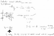
I've derived it in the following attachment if you can read it.
Attachments
- Status
- This old topic is closed. If you want to reopen this topic, contact a moderator using the "Report Post" button.
- Home
- Amplifiers
- Class D
- The "Leap-Frog" Method Of Switching Amplifier Control Loop Design