And now with the 6C33...
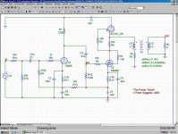
This is the first prototype as built ("rev. 1"). For a misunderstanding, I got a PT with too much voltage on the secondary for the B+, so I got way too much HV on the 6C33 (in the first place I intended to have a pretty much "standard" 220V/200mA operating point for it).
Here follows the schematic:
This is the first prototype as built ("rev. 1"). For a misunderstanding, I got a PT with too much voltage on the secondary for the B+, so I got way too much HV on the 6C33 (in the first place I intended to have a pretty much "standard" 220V/200mA operating point for it).
Here follows the schematic:
Attachments
1st prototype, simulation...
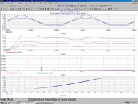
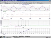
Here are the simulation results. Actual measurements on the prototype were quite in accordance with the simulations. The only relevant exception, as expected, was about distorsion; while the simulation shows almost only 2nd harmonic (at least until clipping), the real world measurements had the usual "forest" of higher order harmonics too. Indeed, all well below the 2nd one and with the "usual", nice monotonically decreasing envelope typical of SETs.
As expectable (given the wrong operating point), efficiency was quite bad: something less than 8W @ 5% THD. Yet the sound was surprisingly good!
Measured output impedance was less than 1 ohm.
Attachments
Then the seek for a new driver begun...
After various tests with the PCL82, I started trying to find out a better suited driver, trying to exploit some distorsion cancellation to reduce the overall output distorsion and increase the useable power / efficiency.
I have done countless simulations with all possibly suitable tubes for which I have found a SPICE model, and actually built a new test driver "board" (which have been "piggy-back" installed on the prototype) to actually test the most promising ones. On the board I have used a 6N1P as the input stage, while as the driver to date I have tested 6N30, 6N1P and 5687.
Sadly ('cause simulations were promising), the 6N30 simply can't take enough plate voltage to work on this circuit, and had to be discarded. The 6N1P could just do it, but in this circuit and with the required operating point they start to clip way too early. No way.
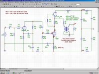
Next went the 5687. Here is the new schematic:
After various tests with the PCL82, I started trying to find out a better suited driver, trying to exploit some distorsion cancellation to reduce the overall output distorsion and increase the useable power / efficiency.
I have done countless simulations with all possibly suitable tubes for which I have found a SPICE model, and actually built a new test driver "board" (which have been "piggy-back" installed on the prototype) to actually test the most promising ones. On the board I have used a 6N1P as the input stage, while as the driver to date I have tested 6N30, 6N1P and 5687.
Sadly ('cause simulations were promising), the 6N30 simply can't take enough plate voltage to work on this circuit, and had to be discarded. The 6N1P could just do it, but in this circuit and with the required operating point they start to clip way too early. No way.
Next went the 5687. Here is the new schematic:
Attachments
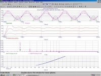
The 5687 seems to work more or less acceptably, but there is a problem. To avoid them to end up with the grid positive (and clip) too early, I had to increase their plate resistor, thus reducing their plate current... way too much to properly drive the 6C33. 
Oddly enough, in some way the "real thing" works a bit better than the simulation, and I can reach around 12 - 13 Wrms with only 22 Kohm on the plate, which is much better than the >39K that seems to be needed according to the simulation.
Yet IMHO it's still way too much to get enough driver current. I would need at least two 5687 sections in parallel to get a barely acceptable driver current...
Simulation result:
Attachments
I need your HELP!!!
Now I'm kind of stalled... being not sure on what to do next.
Using one 5687 (with 22K), in spite of the really low current (~3mA!) the amplifier it is not behaving (both measurement- and sound-wise) as badly as one would expect... yet, the max output power is a bit less than optimal, and with the previous driver using the PCL82 (I would say obviously...) the amplifier sounded much more "fast" and "dynamic", had a much better "PRAT", was more involving... in one word, it was much more enjoyable.
I can go on and try with two 5687 sections in parallel. I guess that doubling the total driver current should solve the "speed" problems.
Yet, I'm not too enthusiastic about this idea.
For one, I'm afraid that even with two 5687 sections in // the power output will still be less than optimal; I may need to go up with the resistance, reducing again the current... then what, add more and more tubes in parallel!?
Second, I don't like the idea of operating triodes in parallel.
Or I can simply just go back to the PCL82, forget about distorsion cancellation and extra power (which after all I don't really need) and live happy.
But it must be possible to do something better...!!!
What I would really need now are some good suggestions for a suitable driver tube... and if you also have a SPICE model for it, that would be really great!
I need your HELP!!!
...and if you want to make some tests yourself, here is the MC8 .cir:
Now I'm kind of stalled...
being not sure on what to do next. Using one 5687 (with 22K), in spite of the really low current (~3mA!) the amplifier it is not behaving (both measurement- and sound-wise) as badly as one would expect... yet, the max output power is a bit less than optimal, and with the previous driver using the PCL82 (I would say obviously...) the amplifier sounded much more "fast" and "dynamic", had a much better "PRAT", was more involving... in one word, it was much more enjoyable.
I can go on and try with two 5687 sections in parallel. I guess that doubling the total driver current should solve the "speed" problems.
Yet, I'm not too enthusiastic about this idea.
For one, I'm afraid that even with two 5687 sections in // the power output will still be less than optimal; I may need to go up with the resistance, reducing again the current... then what, add more and more tubes in parallel!?
Second, I don't like the idea of operating triodes in parallel.
Or I can simply just go back to the PCL82, forget about distorsion cancellation and extra power (which after all I don't really need) and live happy.
But it must be possible to do something better...!!!
What I would really need now are some good suggestions for a suitable driver tube... and if you also have a SPICE model for it, that would be really great!
I need your HELP!!!
...and if you want to make some tests yourself, here is the MC8 .cir:
Attachments
Hi Paolo,
maybe you could narrow in the requirements (mu, rp, gm, current handling capabilities at op point, and so on) what is needed/suitable for the driver tube, so we can make suggestions.
At my site you can find quite some plate curves of triode strapped pentodes (or pentode sections of compound tubes like ECL82 and so on) so you could verify your computer simulations using real world plate curves. Spice simulations often are far from reality.
For other compound tubes in the ECL82 class, but much better linearity, have a look at triode strapped ECL86 and ECL805 there.
Tom
Tubes4e4 said:
maybe you could narrow in the requirements (mu, rp, gm, current handling capabilities at op point, and so on) what is needed/suitable for the driver tube, so we can make suggestions.
Well, the problem is... I'm not really sure of what to look for, that's why I'm asking for help!
( otherwise I could have easily searched for a suitable tube... e.g. using the "parametric search" feature of Duncan's freely downloadable "TDSL"
)What I know for sure is that I need a tube which must be able to provide an output voltage of at least 180Vpp across its plate (totem middle) resistor, that's like to say that it must be able to provide >= 450Vpp on it's plate, with a negative supply <= 350V (the positive supply provides for the remaining required voltage via the totem connection; driver plate swing will be something like -300V to +150V - or even more).
All of this with a plate current >= 6mA, that is with a plate resistor <= 10 Kohm.
(the constrain being that the voltage across the plate resistor -the totem middle one- must obviously be equal to the 6C33 Vgk BIAS voltage, which is around -65V at the desired operating point).
This also means that the driver must be able to provide over 3 Wpp (0.4 Wrms). It's a small power amplifier on it's own!
Oh, I was about to forget the most important thing... the driver must provide its full output with a 2nd harmonic distorsion of about 12 - 15%
in order to provide suitable distorsion cancellation with the output tube! The PCL82 based driver can supply the required voltage swing with enough current, but it does that with... too little distorsion!

Using 5687 (or 12BH7) as driver can provide about the required voltage swing with about the right amount of distorsion, but with way too little current.
What I would need may be a tube with characteristics similar to that of a few (3-4) sections of 5687 or 12BH7 in parallel.
P.S.: thanks for the link, very interesting. How did you get the curves? Have you measured them yourself?
Whenever I see the need to increase a plate resistor and would rather an alternative, I think of using two triodes in parallel. This brings Vgk down as you expect.
I think this is not uncommon. I do it often. Common sense tells us to ensure the triodes are similarly matched.
You may already have most of the power you are going to get, and just need that little extra. If it were me, I would just parallel the 5687's and listen, play and learn the circuit in practise. I'd reckon it would just come to me one day.
If you're looking for a low Rp device, lower than 5687, you may be left with power triodes.
I have been poking around some old documentation and noticed John Broskie talking about SRPP. He said the middle resistor (Rak) is responsible for balance. It has to be right for the load.
I am guessing if you get this right, you will then be left to adjust the current running through it to achieve the correct bias for the 6c33.
- Status
- This old topic is closed. If you want to reopen this topic, contact a moderator using the "Report Post" button.
- Home
- Amplifiers
- Tubes / Valves
- The "PowerTotem"... a new way to SET?